TENTECH MPK254 Manuale utente

Formato: 137mm x 190mm
P. 17
P. 03
Manual de uso
Micro-ohmímetro digital
Digital micro-ohmmeter User guide
www.tentech.com

3
MPK-254
Digital micro-ohmmeter
User’s guide
GF-2045
© 2016 TENTECH. All rights reserved.

4
Safety Precautions
•This equipment should be operated only by qualified and duly trained people,
closely observing the corresponding safety regulations and instructions
contained in the present User guide.
•It should be checked that the item to be measured is voltage free.
•Before starting with the measurements, be sure that the battery is well charged
and that the line voltage is between specified limits.
•Do not connect or disconnect the test leads during the measurement.
•There are no adjustable parts or parts that can be replaced by the user within the
equipment. Taking out the Control Panel in order to have an access to the
internal parts may be dangerous as there are high voltages inside, capable of
causing fatal accidents.
•Cleaning of this instrument should be carried out using a soft cleaning liquid,
after verifying that it doesn't attack the plastic parts used in the case and in the
Control Panel of this equipment.
This equipment should be used only by a trained and competent
person, strictly applying suitable safety rules.
Used symbols
Caution, refer to User Guide.
Equipment complies with current EU Directives.
The rubbish bin with a line through it means that in the European Union,
the product must undergo selective disposal for the recycling of electric
and electronic material, in compliance with Directive WEEE 2002/96/EC.

5
Index
1. Description......................................................................................................... 6
1.1. Operating principle...................................................................................... 6
2. Control panel ..................................................................................................... 7
3. Power supply ..................................................................................................... 8
3.1. Battery condition ......................................................................................... 8
3.2. Battery charger ........................................................................................... 8
4. Measurement..................................................................................................... 9
5. Messages ........................................................................................................ 10
6. Some notes about accuracy............................................................................. 12
7. RS232 output................................................................................................... 13
8. Cleaning .......................................................................................................... 13
9. Replacement fuse............................................................................................ 13
10. Technical specifications ................................................................................. 14
11. Warranty........................................................................................................ 16

6
1. Description
The MPK-254 micro-ohmmeter is a portable, microprocessor controlled
instrument, used to accurately measure very low contact resistances of
breakers and switches, busbars, transformers and engines windings, etc,
with test currents from 1 mA to 5 A.
•Kelvin architecture (four-terminal method).
•Digital reading, alphanumeric display.
•Up to 4½ digits readings.
•Powered by rechargeable battery.
•1 µresolution.
•200 maximum reading.
1.1. Operating principle
This device uses the Kelvin Bridge architecture, with four terminals,
avoiding testing leads resistance to cause error during measurement. The
operator may choose test current and the reading is obtained by
comparison through internal high-stability standards. The result appears
in the alphanumeric display that is very easy to read.

7
2. Control panel
5
4
32
1
6
7
89
Fuse.
Power cord connector.
On/Off switch.
Battery charge indicator.
Current terminal (C+).
Potential terminal (P+).
Potential terminal (P-).
Current terminal (C-).
RS232 data output.
Alphanumeric display. Shows both
the measured resistance value and
messages to the operator.
Start key.
Stop key.
Hold key. It retains the last
measurement in the display.
Battery key. To measure the battery
charge condition.
Test current control.
Range and test current selector.
On led.

8
3. Power supply
Internal battery powered, rechargeable, 12 V - 7 Ah.
At the end of the useful life, the battery has to be recy
cled or disposed of
properly in order to take care of the environment.
3.1. Battery condition
The charge condition of the battery can be verified before or during the
resistance measurement. In order to achieve that, the operator has to
press the battery key while the equipment is turned on. The bargraph
shows remaining charge as a percentile value. If during measurement the
charge of the battery achieves a critical level, the display will show the
BAT message notifying that the charge level is low. After a few minutes
the measurement will be automatically interrupted in order to preserve the
battery from a deep discharge that is prejudicial for its expected useful
life.
3.2. Battery charger
The built-in battery charger is always active when the equipment is
connected to the mains supply, even if the On/Off switch is turned off.
Charging procedure:
•Check that the On/Off switch is in Off.
•Connect the equipment to the mains supply.
•The battery charge indicator will keep on lightning with a red light
up to completing the charge. At that point, it will change to a green light,
being like this up to the equipment disconnection from the mains supply.
If the ON/OFFswitch was pressed, the display will indicate
CHARGING BAT.
9
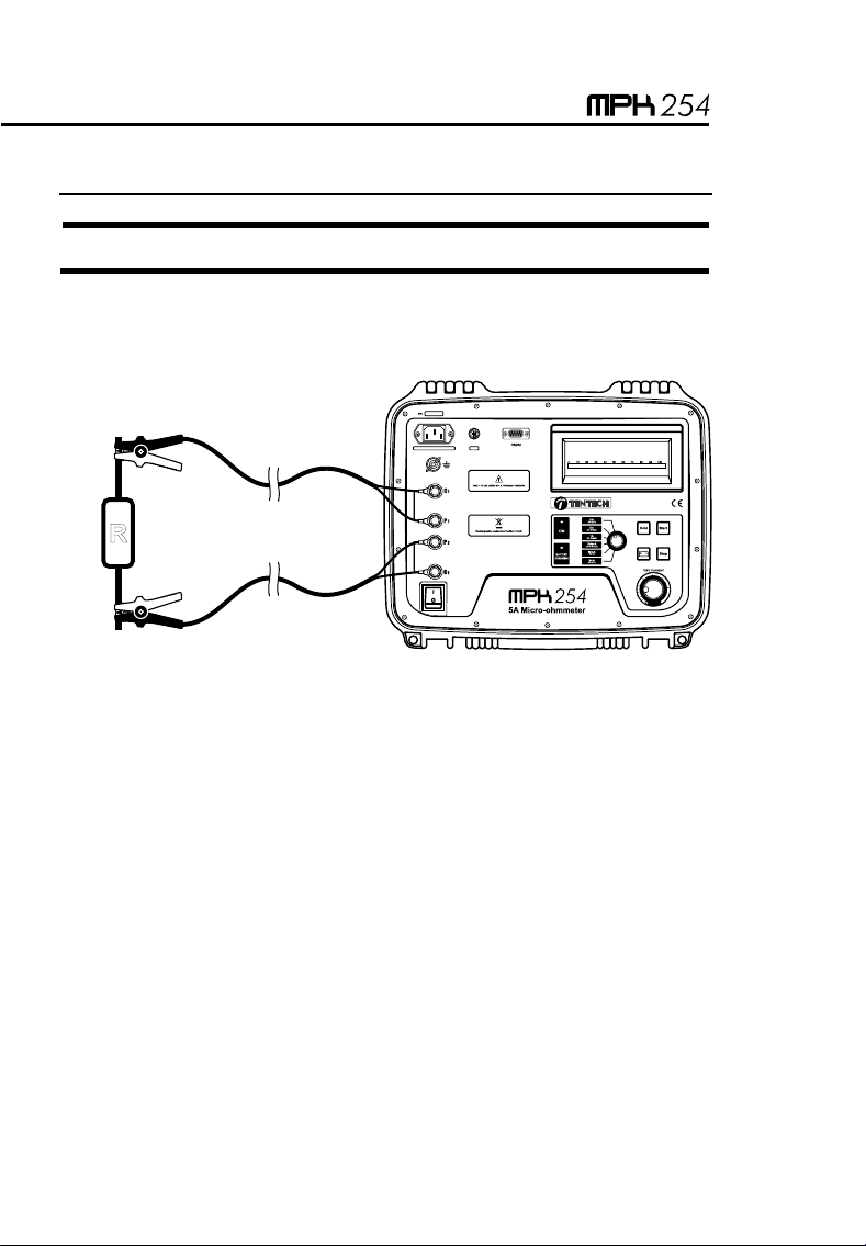
4. Measurement
It should be checked that the item to be measured is voltage free.
1. Before turning the equipment On, connect the test leads to the item to
be measured and to the front panel terminals.
5
4
32
1
6
7
89
R
The alligator clamps in the drawing are only for illustration.
2. Using the test current selector , choose the range and the current
to be used.
3. Switch the equipment On using the On/Off .
4. The PRESS START message will appear showing that measurement
can be started. Press the Start key. Depending on the position of
the test current control the LOW CURRENT message will turn
up.
5. Turning the test current control clockwise increases the current.
Adjust this control until obtaining the desired value or until the current
indicator (bargraph) indicates 100%. The bargraph will show the test
current value as a percentage of the nominal value selected by using
the test current selector .

10
6. The lowest current for measuring is 10% of the nominal value. It is
important to consider that the measurement errors increase while test
current decreases. The equipment accuracy is specified for test
currents higher than 80%.
7. The display will show the resistance value measured and the
corresponding unit ([ohms], m[milli-ohms] or µ[micro-ohms]).
8. The value can be retained in the display by pressing the hold key.
Pressing this key again, the value will be released.
9. Press the Stop key in order to finish the measurement. Do not turn
Off the equipment without pressing the Stop key before.
10. Finally, when finishing measurements, turn the equipment Off using
the On/Off switch.
Precaution:
Do not connect or disconnect the test leads during the
measurement.
5. Messages
TENTECH MPK-254
When turning the equipment On using the On/Off switch, this
introductory message appears for a while.
WAIT...
This message appears each time the equipment needs to adjust any
parameter in order to optimize the readings.
PRESS START
The equipment is ready to start a measurement, thus the operator has to
press the Start key.

11
LOW CURRENT
It shows that the test current is not enough to carry out the reading. It
appears at the beginning of each test and it keeps on being there up to
the operator rotates the test current control clockwise, as necessary
for the test current to be higher than 10 % of the nominal current in the
range. The inappropriate connection of the cables may cause a difficult
circulation of test current. If this message keeps on being displayed,
please check that the current cables are connected appropriately.
OVERRANGE
It indicates that the measured resistance is higher than the maximum
value readable in the selected range.
H
Indicates that the value is the one retained in the display when pressing
the hold key.
BAT
It shows that the battery is quite discharged. It is necessary the battery to
be recharged.
CHARGING BAT
It appears when the equipment is connected to mains supply and the
ON/OFswitch, is ON.
Indice
Lingue:


