UEi DL579 Manuale utente

CAT III
600V 600A
DL579
NCV
Low Z
V
µA
°F °C
TEMP
V
mV
CATIII 600V
CATIV 300V
True RMS
DISCONNECT TEST LEADS
30V MAX
SELECT INRUSH
RANGE MAX/MIN
AUTO
AT µ
INSTRUCTION MANUAL
ENGLISH
DL579
Digital HVAC Clamp Meter
w/ CATIII 600V
1-800-547-5740
300V
CAT IV
600V
CAT III

2
Table Of Contents
FUNCTIONS............................................................................................3
FEATURES .............................................................................................3
GENERAL SPECIFICATIONS .............................................................3
IMPORTANT SAFETY WARNINGS ................................................. 4
SYMBOLS .............................................................................................5
CATEGORY DEFINITIONS...................................................................5
OVERVIEW ..................................................................................... 6 - 7
OPERATING INSTRUCTIONS
Low Z (Low Impedance) ........................................................... 7
AC Amps: <600A – Jaw .......................................................... 8
Non-Contact Voltage................................................................ 9
AC/DC Microamps: <2000μA ............................................... 10
Temperature F˚/C˚ .....................................................................11
Continuity ..................................................................................12
Resistance: < 60MΩ .................................................................12
Capacitance................................................................................13
Diode .........................................................................................14
AC Voltage: 750V AC ............................................................. 15
DC Voltage: 1000V DC................................................................16
Frequency/Hz/Duty Cycle(%).....................................................17
LRA Inrush ..................................................................................18
Test Lead Notes .........................................................................19
Battery Replacement .................................................................19
WARRANTY.........................................................................................20
DISPOSAL ...........................................................................................20
CLEANING ...........................................................................................20
STORAGE ...........................................................................................20

3
Functions
Features
• True RMS
• 750V AC/1000V DC
• 600A AC
• AC/DC microamps: 2000µA
• Capacitance: 6000µF
• Frequency: 99.99kHz
• Duty cycle
• Diode test
• Audible continuity
• NCV
• LRA Inrush
• Temperature range: -328˚ to 2462˚F
• Resistance: 60MΩ
• Low Z (Low Impedance)
• Dual display
• Auto/Manual ranging
• Back light
• Low battery indicator
• Data Hold
• Auto power off
• Test lead storage
• Auto calibration
• Built-in Magnet w/hanging strap
(Optional)
• Visible high-voltage alert
• Input jack locks
• Min/Max
• Battery compartment latches
General Specifications
•Operating Temperature: 32˚ to 122˚F (0˚ to 50˚C)
•Storage Temperature: -4˚ to 140˚F (-20˚ to 60˚C)
•Operating Humidity: <80%
•Pollution Degree: 2
•Display: 3 5/6 digits 6,000 count
•Back light: Yes
•Refresh Rate: 3/sec
•Over-range: “OL” is displayed
•Apo: Auto power off after 30 minutes of use.
•Dimensions: 8.7” x 2.52” x1.41”
•Item Weight: 0.65 lb
•CAT Rating: CATIV 300V, CATIII 600V
•Certifications: cETLus UL 61010-1: 2012, IP42
•Battery Type: (AAA) 2
•Test leads: Test lead ATL55 w/alligator clips

4
Important Safety Warnings
WARNING
Read entire Safety Notes section regarding potential hazards and proper
instructions before using this meter. In this manual the word “WARNING” is
used to indicate conditions or actions that may pose physical hazards to the
user. The word “CAUTION” is used to indicate conditions or actions that may
damage this instrument.
WARNING
To ensure safe operation and service of the tester, follow these instructions.
Failure to observe these warnings can result in severe injury or death.
WARNING
• Before each use, verify meter operation by measuring a known voltage or
current.
• Never use the meter on a circuit with voltages that exceed the category
based rating of this meter.
• Do not use this meter during electrical storms or in wet weather.
• Do not use the meter or test leads if they appear damaged.
• Ensure meter leads are fully seated and keep fingers away from the metal
probe contact when making measurements. Always grip the leads behind
the finger guards molded into the probe. For information on test lead shields
instructions on page 19.
• Do not open the meter to replace batteries while the probes are connected.
• Use caution when working with voltages above 60 DC or 25 AC RMS. Such
voltages pose shock hazards.
• To avoid false readings that can lead to electrical shock, replace batteries if
a low battery indicator appears.
• Unless measuring voltage or current, shut off and lockout power before
measuring resistance or capacitance.
• Always adhere to national and local safety codes. Use proper personal
protective equipment (PPE) to prevent shock and arc blast injury where
hazardous live conductors are exposed.
• Always turn off power to a circuit or assembly under test before cutting,
unsoldering or breaking the current path. Even small amounts of current
can be dangerous.
• Always disconnect the live test lead before disconnecting the common test
lead from the circuit.
• In the event of electrical shock, ALWAYS bring the victim to the emergency
room for evaluation, regardless of victim’s apparent recovery. Electrical
shock can cause unstable heart rhythms that may need medical attention.
• If any of the following occur during testing, turn off the power source to the
circuit being tested: arcing, flame, smoke, extreme heat, smell of burning
materials or discoloration or melting of components.
WARNING
Higher voltages and currents require greater awareness of physical safety
hazards. Before connecting the test leads; turn off power to the circuit under
test, set meter to the desired function and range; connect the test leads to
the meter first, then connect to the circuit under test. Reapply power. If an
erroneous reading is observed, disconnect power immediately and recheck all
settings and connections.
WARNING
This meter is designed to provide HVAC/R technicians with the capabilities they
need to diagnose and repair HVAC/R system. Observe all recommended
safety procedures that include proper lockout utilization and use of personal
protective equipment that includes safety glasses, gloves and flame resistant
clothing.

5
Symbols
AC (Alternating current) DC (Direct current)
Negative AC/DC Voltage or Current
Auto-ranging
Overload: Range Exceeded
Auto power off Active Non-Contact Voltage
Low Battery Hold/Capture Value
Minimum measured
value displayed
Maximum measured
value displayed
Duty Cycle Hertz/Frequency
Voltage Inrush
Amperage Ohms/Resistance
Diode Capacitance
Nanofarad
µF
Microfarad
Microamps Continuity
Degrees Fahrenheit Degrees Celsius
Mega (x106or 1,000,000) Milli (x10-3 or 0.001)
Kilo (x103or 1,000) Micro (x10-6 or 0.000001)
Warning or Caution Ground
Dangerous Levels Double Insulation
(Protection to Class II)
Safe for disconnect from
live conductors No reading detected
k
Kilo Ohms
EF
Electric Field
Measurement
Category
Short-Circuit
(typical) kA
a
Location in the
building installation
II < 10 Circuits connected to mains socket
outlets and similar points in the MAINS
installation
III < 50 Mains distributions parts of the building
IV > 50 Source of the mains installation in the
building
Category Definitions

6
A. Clamp: Measure inductive AC current. Opens to 1.25” (32.0mm).
B. Conductor Alignment Marks: Use to aid the visual alignment of a
conductor when measuring inductive amperage. Greatest accuracy
is achieved when the conductor inside the clamp is centered at the
intersection of these marks.
C. Category Max Indicator: Maximum CAT Rating for clamp jaw.
D. NCV Alert Light: Indicates voltage when in NCV (Non Contact Voltage)
mode and High Voltage alert.
F. Clamp Lever: Opens and closes current clamp jaw.
NOTE: The clamp uses a high-tension spring to close the jaw. Do not
allow fingers or objects to become pinched in the base as the jaws close.
G. Rotary Selector Dial: Set Rotary Selector Dial desired function
H. Range Button:
• Press to set manual range desired
I. SELECT Button:
• Press AC or DC on Low Z setting; DCmV or DCV on Voltage setting;
to activate ohms, Continuity, Diode, Capacitance on Ohms/Continuity/
Diode/Capacitance setting; AC or DC on μA setting; °C or °F
temperature setting
J. Category Max Indicator: Maximum CAT Rating for input jacks.
K. Test Lead Input Jacks: Multifunction and Positive input jacks.
• Multifunction input port used for measuring: AC or DC volts, resistance,
continuity, diode, capacitance, AC or DC μA.
L. Wire Separation Tab/ NCV sensor: Use to isolate an individual wire from
a bundle for testing. NCV sensor detects live voltage.
M. Test Lead Holder
N. Hand Guide: Used as a point of reference for the operator’s safety.
O. Hold/Back light Button:
• Press to hold the reading on the display. Press again to return to live reading.
• Press and hold to turn on Back light.
• Backlight turn off after 60 seconds.
• Press hold during power up to disable the Auto power off function.
Overview
V
X
W
CAT III
600V 600A
DL579
NCV
Low Z
V
µA
°F °C
TEMP
V
mV
CATIII 600V
CATIV 300V
True RMS
DISCONNECTTEST LEADS
30VMAX
SELECT INRUSH
RANGE MAX/MIN
AUTO
AT µ
L
M
N
I
J
Q
R
P
A
C
F
K
D
G
H
B
O
S
T
U
7
P. Min/Max Button:
• Press to enter MIN/MAX mode.
• Step through maximum(MAX), minimum(MIN) and present values.
• Press and hold return to Live readings
Q. Display:
• High contrast dual display with backlit.
• AC Amps reading will always display on upper display.
R. Inrush/Hz Duty Button:
• Press to enter LRA Inrush mode (See page 18 for details)
(must be in AC Amps mode first).
• Press again to return to live readings.
• Press and hold to select Hz/Duty in AC volt or AC µA.
S. K-Type Temperature Probe Inputs
T. Input Jack Lock: Switch to use Temperature or Test lead inputs
U. Built-in versatile magnet to use as a mount or as a strap (optional)
V. Battery Cover: Easy access for replacing batteries without breaking
calibration seal.
W. Battery Compartment Latches
X. Serial Number
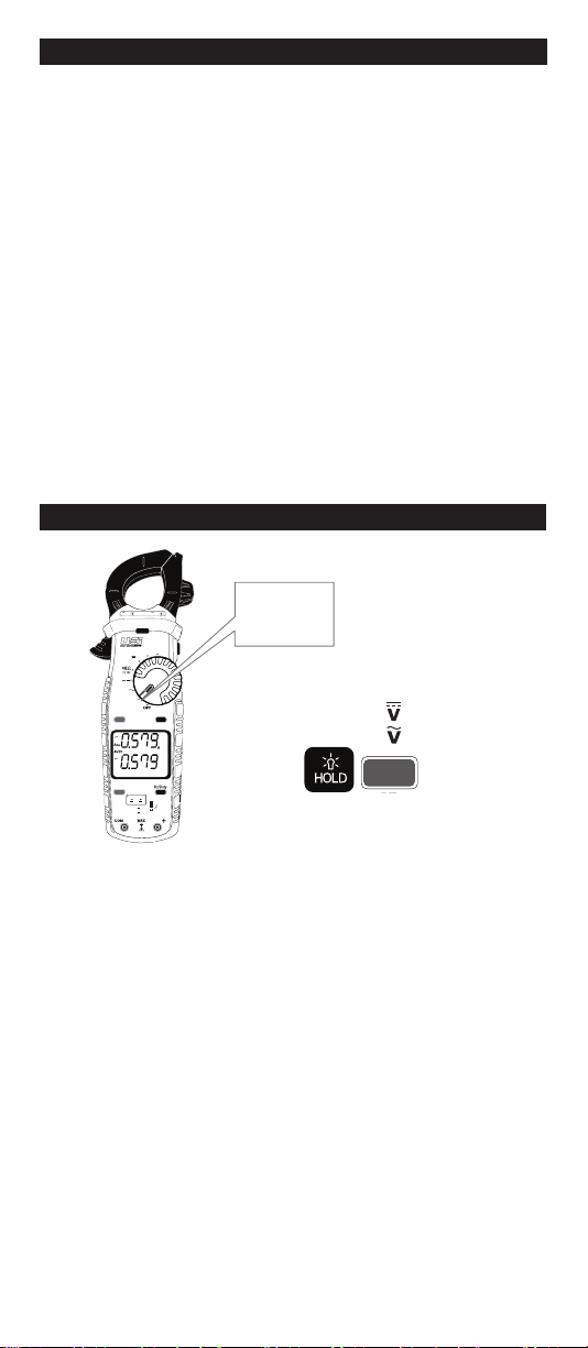
Overview (Cont.)
Low Z (Low Impedance)
•
Rotate Selector Dial to Low Z
• Default = Auto Selection (DC or AC)
• Press SELECT x1 =
• Press SELECT x2 =
Features:
BT
SELECT
CAT III
600V 600A
DL579
NCV
Low Z
V
µA
°F °C
TEMP
V
mV
CATIII 600V
CATIV 300V
True RMS
DISCONNECTTEST LEADS
30VMAX
SELECT INRUSH
RANGE MAX/MIN
AUTO
AT µ
Low Z
V
Low Z

8
CAT III
600V 600A
DL579
NCV
Low Z
V
µA
°F °C
TEMP
V
mV
CATIII 600V
CATIV 300V
True RMS
DISCONNECTTEST LEADS
30VMAX
SELECT INRUSH
RANGE MAX/MIN
AUTO
AT µ
CAT III
600V 600A
DL579
NCV
Low Z
V
µA
°F °C
TEMP
V
mV
CATIII 600V
CATIV 300V
True RMS
DISCONNECTTEST LEADS
30VMAX
SELECT INRUSH
RANGE MAX/MIN
AUTO
AT µ
Single
Conductor
Only
AC Amps <600A Jaw
• AC Amps can be measured in any position of the rotary selector dial.
• Center wire in guides for best accuracy.
• Opposing currents cancel each other (use line-splitter when necessary).
• Keep hands below guard when measuring high current levels.
• Do not attempt to measure more than 600A AC.
Features:
AC Amps Measurement - Jaw input
Range Resolution Accuracy Overload Protection
60.00A 0.01A ±2.0% + 8dgts 600V RMS
600.0A 0.1A
45Hz to 400Hz True RMS
Minimum Current for Clamp Measurement: 0.3A
• Rotary selector dial =
any position
• Reading show on
upper display
V
Low Z

9
Non-Contact Voltage
NCV Sensor in the tip.
CAT III
600V 600A
DL579
NCV
Low Z
V
µA
°F °C
TEMP
V
mV
CATIII 600V
CATIV 300V
True RMS
DISCONNECTTEST LEADS
30VMAX
SELECT INRUSH
RANGE MAX/MIN
AUTO
AT µ
• Rotate Rotary Selector Dial to NCV position move the tip of the clamp meter
near voltage source.
• Non-Contact Voltage Detection is used to detect power with sensor located
in the tip of the clamp head, indicates positive response with both an
Audible and Visual alert.
• Do not use Non-contact voltage detector to determine if there is current on
the wire. Detection operation could be affected by socket design, insulation
thickness, type or other factors.
• Voltage indicator light may also light when voltage (>AC/DC 30V) is present
on the meter’s input jack or from an external interference such as motors,
flashlights, etc.
Features:
On Voltage
Approx. 24V AC
AUTO
10
CAT III
600V 600A
DL579
NCV
Low Z
V
µA
°F °C
TEMP
V
mV
CATIII 600V
CATIV 300V
True RMS
DISCONNECTTEST LEADS
30VMAX
SELECT INRUSH
RANGE MAX/MIN
AUTO
AT µ
AUTO
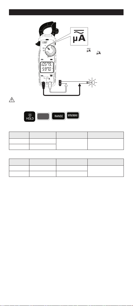
µ
• Default =
• Press SELECT =
• Readings show on lower display
AC/DC Microamps: <2000µA
WARNING
• Do not attempt to measure more than 2000µA.
Features:
BT
SELECT
DC Microamps Measurement -Test lead input
Range Resolution Accuracy Overload Protection
600.0uA 0.1uA ±1.2% + 3dgts 600V RMS
2000uA 1uA
AC Microamps Measurement -Test lead input
Range Resolution Accuracy Overload Protection
600.0uA 0.1uA ±2.0% + 5dgts 600V RMS
2000uA 1uA ±1.5% + 5dgts
45Hz to 400Hz True RMS
Indice
Altri manuali UEi Strumento di misura


