
Vega ALT-5 Manuale utente

Introduction
The ALT-5 is a 2 1/4” (57mm) sunlight readable encoding altimeter and a wide range ertical speed indicator.
The altimeter contains an internal high accuracy 24 bit digital altitude sensor which calculates altitude from -1500 ft up to
a maximum of +35000 ft. The ALT-5 outputs arious formatted RS232 serial data protocols compatible with serial input
transponders such as that from Garmin, Magellan, Northstar, Trimble, Microair etc. The altimeter can display altitude in
feet or meters and local pressure can be set in millibars or inches of mercury
The VSI indicator can be displayed in either feet/minute (ft/min) or meters/second (m/s). The VSI can be calibrated by the
user once the instrument has been installed in the aircraft.
The ALT-5 also features a user settable altitude bug and an encoder test function. The ALT-5 pro ides a parallel Gillham
code interface when used in conjunction with the MGL A ionics CNV-ALT.
1 Features
•Large 1.8” high resolution 160x128, wide viewing angle, sunlight readable, 1000 cd/m2 color LC display
• An internal high accuracy 24 bit digital altitude sensor calculates altitude from –1500 ft up to a maximum
of 35000 ft (-457m to 10668m)
• The ALT-5 outputs various formatted RS232 serial data protocols compatible with serial input
transponders such as that from Garmin, Magellan, Northstar, Trimble, Microair etc.
• Provides a parallel Gillham code interface for transponders when used in combination with the MGL
Avionics CNV-ALT
• Built in encoder test function
• The altimeter can display altitude in feet or meters
• Local pressure can be set in millibars or inches of mercury
• Contains a wide range VSI indicator from /-20 ft/min to as high as /-10000 ft/min
• VSI units can be in feet/minute (ft/min) or in meters/second (m/s)
• User settable altitude bug
• Standard 2 1/4” (57mm) aircraft enclosure (can be front or rear mounted)
• Rotary control plus 2 independent buttons for easy menu navigation and user input
• Wide input supply voltage range of 8 to 30V DC
• 1 year limited warranty
Vega ALT-5
Altimeter and Vertical Speed Indicator
with a transponder compatible serial
RS232 output
Operating Manual – English 1.06
Vega ALT-5 Operating Manual Page 2
2 Layout
3 Main Displays
The ALT-5 has 2 different display screens. The main display screen can be selected in the “ALT SETUP” menu.
3.1 Altitude "TAPE" Display
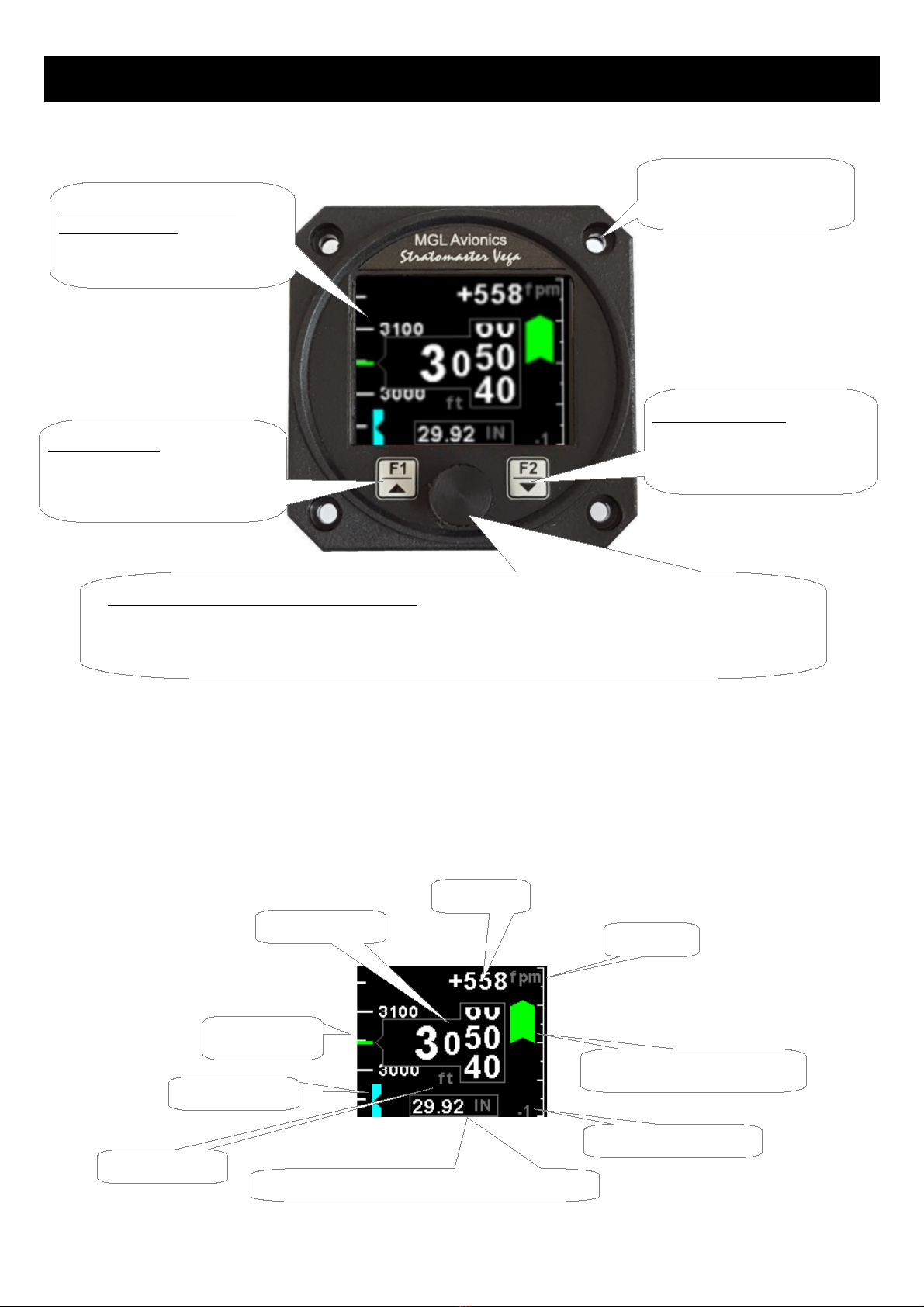
F2 / Down Button:
Menu system: Softkey button
Normal display: Altitude
bug setting display
Sunlight readable color
graphic display:
Backlight can be adjusted in the
menu system
Rotary Control (Up/Down) & Enter Button:
Press the rotary control during the normal display screens to access the menu system. Rotate anti/clockwise
for up/down menu scrolling. Rotate the rotary control during the normal display mode to adjust the local
pressure. Local pressure can be set in either mB or in “Hg.
F1 / Up Button:
Menu system: Softkey button
Normal display: Enable/disable
altitude bug
2 1/4” (57mm) enclosure.
Can be front or rear mounted
VSI scale indication
VS I (Vertical Speed Indication)
VSI unit
Altitude Tape
Altitude Value
Altitude Bug
Local pressure readout (Either in mB or in “HG)
VSI Value
Altitude unit
Vega ALT-5 Operating Manual Page 3
3.2 Altitude "CLASSIC" Display
3.3 Altitude Bug
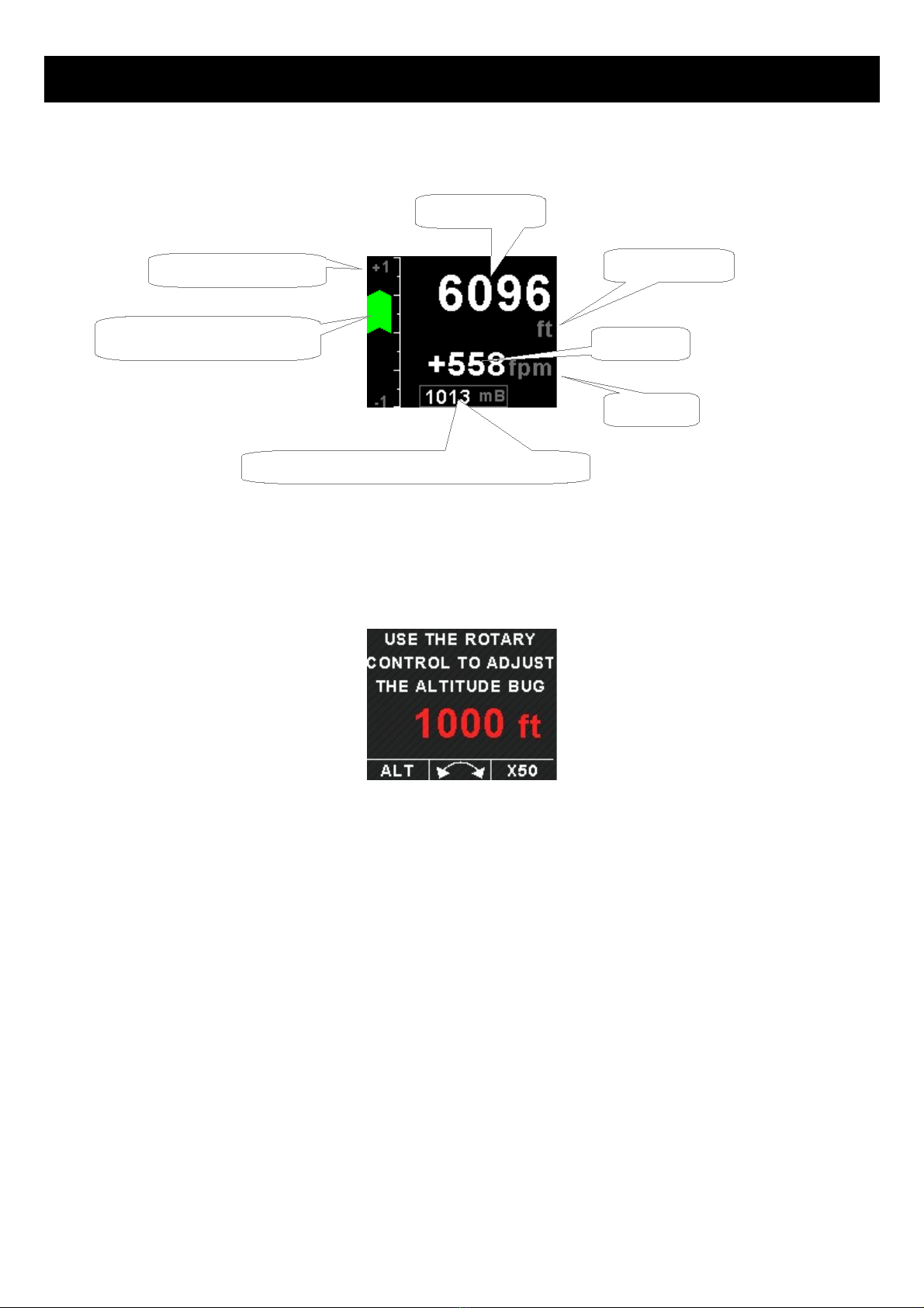
Press the F2/Down button during the altitude “TAPE” display to access the altitude bug setting screen. Press the F1/UP
key to set the altitude bug to the current altitude or use the rotary control to adjust the altitude bug. Press the F2/Down
key to change the increment / decrement unit to 50 or 500. Press the rotary control to exit and sa e.
Press the F1/Up button during the normal altitude “TAPE” display to enable or disable the altitude bug. The bug will be
yellow when in the display screen and cyan when either abo e or below the limits of the display.
VSI Value
VSI unit
Altitude unit
Altitude Value
VSI scale indication
VSI (Vertical Speed Indication)
Local pressure readout (Either in mB or in “HG)

Vega ALT-5 Operating Manual Page 4
4 Menu System
Press the rotary control button during the normal display mode to enter the menu system. Use the rotary control to
na igate through the menu system.
4.1 Exiting the menu system
Press the F1/Up button to exit the menu system when the “EXIT” soft key is shown. All changes made during na igation
of the menu system will be sa ed in non- olatile memory upon exiting. The instrument will not sa e any changes if you
remo e power before exiting the menu system.

Vega ALT-5 Operating Manual Page 5
4.2 ALT Setup (Altitude Setup)
Style:
Select the altitude display screen. Options include “TAPE” or “CLASSIC”.
Altitude Unit:
Select if you want the altitude displayed in ft (feet) or m (meters).
Pressure Unit:
Select if you want the local pressure displayed in mb (millibars) or “Hg (inches of mercury).
Resolution:
Select the resolution of the altitude alue, a selection of 1,10,25 or 100 ft or m can be selected.
ALT Calibrate
This section allows for the calibration and fine tweaking of the altitude alue. Before you begin, ensure that your calibrated
and certified reference is set to the local pressure of 1013.25mB (29.92”Hg). The ALT-5 altitude alue in ft (referenced to
1013.25mB (29.92”Hg)) is displayed in the top right hand corner of the display. All calibration must be done in feet.
The combined adjustments cater for both the altitude sensors offset and gain. Only start the calibration sequence once
the instrument has been running for a minimum of 10 minutes.
Start the altitude calibration with the “CAL FACTOR” and make sure the “CAL GAIN” alue is set to 100.00%.

Vega ALT-5 Operating Manual Page 6
Cal Factor:
On the rear of your ALT-5 instrument you will find the calibration factor that has been determined to ensure the most
accurate reading of your altimeter. This is the pressure sensor offset in 0.1mB increments. Adjust your static pressure to
be close to sea le el pressure. The exact altitude is not important and can be up to se eral hundred feet. Adjust the
calibration factor so the altitude readout in the top right hand corner of the display agrees with your pitot static test set.
Cal Gain:
Once you are satisfied that the low le el altitude “CAL FACTOR” is correct, apply a static pressure that will result in an
altitude between 20000 and 30000 ft. Adjust the “CAL GAIN” until the altitude readout in the top right hand corner of the
display agrees with your pitot static test set
NOTE: Adjusting the “CAL GAIN” also changes the low le el altitude calibration achie ed when adjusting the “CAL
FACTOR”. Please recheck your low le el altitude calibration and adjust if necessary. Recheck your altitude readout at the
higher altitude, and if needed slightly adjust the “CAL GAIN” again. Repeat the process until you are satisfied with both
the “CAL FACTOR” altitude and the “CAL GAIN” altitude.
Serial Out:
Select “ON” to enable the RS232 serial altitude output. This formatted serial RS232 message can be directly interfaced to
arious RS232 serial input transponders. If a parallel Gillham output is required then a CNV-ALT can be purchased from
your MGL A ionics distributor to con ert the RS232 output to a parallel Gillham output.
Prot:
Select the protocol of the serial RS232 output message. The protocol can be selected between GARMIN AT, Magellan,
Northstar / Garmin, Trimble / Garmin, MGL A ionics and Microair UAV. Please note that the baud rate is automatically
adjusted according to which protocol is selected. The output format is as follows. The message contains the current
pressure altitude with a fixed reference to 1013.25mB (29.92 inches mercury). All protocols use 8 databits, no parity, and
1 stop bit. The message is outputted once a second.
Protocol Baud
Rate
Message format Example
Garmin AT 1200 #AL, space, +/-, fi e altitude digits right
justified zero padded, T+25, checksum,
carriage return
The checksum is a simple modulo 256 sum
of the binary alues of the indi idual
characters. The checksum is sent as two
characters in hexadecimal format
#AL +02372T+25DF[CR]
Magellan 1200 #MGL, +/-, fi e altitude digits right justified
zero padded, T+25, checksum, carriage
return
The checksum is a simple modulo 256 sum
of the binary alues of the indi idual
characters. The checksum is sent as two
characters in hexadecimal format
$MGL+02372T+2513[CR]
Northstar,
Garmin
4800 ALT, space, fi e altitude digits right justified
zero padded, carriage return
ALT 02372[CR]
Trimble,
Garmin
GTX327,
GTX328,
GTX330
(Set on Icarus)
9600 ALT, space, fi e altitude digits right justified
zero padded, carriage return
ALT 02372[CR]
MGL A ionics 9600 ALT, +/-, fi e altitude digits right justified
zero padded ,1013.25mB (29.92”Hg)
referenced, C, +/-, fi e altitude digits right
ALT+02372C+02372L1013+0000XCA[
CR]

Vega ALT-5 Operating Manual Page 7
justified zero padded (corrected to local
pressure), L, local pressure setting in
millibars,+/-, four digit VSI reading right
justified zero padded in ft/min, X,
checksum, carriage return
The checksum is a simple modulo 256 sum
of the binary alues of the indi idual
characters. The checksum is sent as two
characters in hexadecimal format
Microair UAV 9600 STX,a,=, fi e altitude digits right justified
zero padded, ETX
[STX]a=02372[ETX]
Infiniteq 57600 See Infiniteq protocol format below
STX=0x02
ETX=0x03
CR=0x0D
Infiniteq protocol format:
STX, Address, Message type, Length, Data payload, Checksum, ETX
STX: Start of text (0x02)
Address: unsigned char (8bit), (0x01)
Message Type: unsigned char (8bit), (0x05)
Length: unsigned char (8bit), Length of the data payload (does not include the STX, Address, message type, checksum or
ETX), (0x06)
Data payload:
Altitude: Signed Long (32 bit), Altitude in feet (Referenced to 1013.25mB)
Vertical Speed: Signed Int (16 bit), Vertical Speed in ft/min
Checksum: unsigned char (8bit), XOR of all bytes starting from the unit address to the end of the data payload. The
checksum is seeded with 0xa5. (does not include the STX or ETX)
ETX: End of text (0x03)

Vega ALT-5 Operating Manual Page 8
Test Alt Encoder:
This is a handy function to test the ALT-5 transponder interface once the installation has been completed. The serial
output will output specific altitudes which can then can be used to test the serial RS232 output and the parallel gillham
output if using a CNV-ALT con erter. The ALT-5 will resume the normal output of the indicated altitude upon exiting the
test function.
The following codes are outputted:
Altitude D4 A1 A2 A4 B1 B2 B4 C1 C2 C4
-1000ft 0 0 0 0 0 0 0 0 1 0
-900ft 0 0 0 0 0 0 0 1 1 0
-700ft 0 0 0 0 0 0 1 1 0 0
-400ft 0 0 0 0 0 0 1 0 1 1
-200ft 0 0 0 0 0 1 1 0 0 1
800ft 0 0 0 0 1 1 0 0 0 1
2800ft 0 0 0 1 1 0 0 0 0 1
6800ft 0 0 1 1 0 0 0 0 0 1
14800ft 0 1 1 0 0 0 0 0 0 1
30800ft 1 1 0 0 0 0 0 0 0 1
Each altitude reporting code line must be tested for integrity of connection if at any time the aircraft connections to the
transponder or altitude data source ha e been remo ed and reconnected. Integrity of the connections may be erified by
performing a test of mode C function of the transponder system.
Warning: Do not use this function while in flight as incorrect altitude information will be sent to
the transponder.

Vega ALT-5 Operating Manual Page 9
4.3 VSI Setup (Vertical Speed Indicator Setup)
VSI Dis lay:
Select if you want the VSI display to be shown on the altitude “TAPE” display. The VSI display is always shown on the
altitude “CLASSIC” display.
VSI Unit:
Select if you want the VSI to be displayed in "ft/min" (feet/minute) or "m/s" (meters/second).
Scale:
Select the VSI scale most suited for your aircraft.
VSI Cal:
This is a function that is used to calibrate your VSI to read exact rates of climb or decent. This function works as a
percentage of initial reading. The default setting for this function is 100%. Increasing this alue increases the VSI reading
and decreasing the alue decreases the reading.
Suggested VSI calibration method
After you ha e installed the instrument, perform a calibration flight. This should be done in ery calm conditions.
Turbulence and thermal acti ity will make accurate calibration impossible. Many areas ha e ideal conditions during early
mornings or late afternoons. Place the instrument in ft/min for ease of calibration. Take your aircraft to a few
thousand feet abo e ground and start a glide with a low power setting. Take a stopwatch and when the glide is stable
(stable VSI reading) start the stopwatch. Take note of your altimeter reading at the same time. Continue the stable glide
for one minute exactly. After the minute has finished, take another reading of your altimeter.
Example:
VSI reading during stable glide: -400 ft/min
Start altitude: 2500 ft.
End altitude: 2050 ft.
In the abo e example the VSI is under reading by about 12%. Set your VSI calibration to 112% to cancel out the error.

Vega ALT-5 Operating Manual Page 10
4.4 MISC Setup (Miscellaneous Setup)
Backlight:
Select this menu option to adjust the backlight brightness.
Security Setu :
Select this menu option if you want to password protect the menu system.
Information:
This menu option displays information about the unit.
Indice
Altri manuali Vega Strumento di misura

Vega
Vega VEGASON 61 Manuale utente

Vega
Vega INFO-1 Manuale utente

Vega
Vega VEGACAP 65 Manuale utente

Vega
Vega VEGACAP 64 Manuale utente

Vega
Vega VEGACAL 69 Manuale utente

Vega
Vega VEGACAL 65 Manuale utente

Vega
Vega VEGAFLEX 81 Manuale utente

Vega
Vega VEGAPULS WL 61 Manuale utente

Vega
Vega VEGABAR 66 Manuale utente

Vega
Vega VEGAPULS 66 Manuale utente

Vega
Vega vegacap 62 Manuale utente

Vega
Vega VEGASON 51K Manuale utente

Vega
Vega VEGAPULS 64 Manuale utente

Vega
Vega vegacap 62 Manuale utente

Vega
Vega VEGAFLEX 86 Manuale utente

Vega
Vega VEGAPULS WL 61 Manuale utente

Vega
Vega VEGAMIP U61 Manuale utente

Vega
Vega VEGADIS 61 Manuale utente

Vega
Vega VEGABAR 81 Manuale utente

Vega
Vega VEGAWAVE Schema elettrico


