AllyNav R51 Manuale utente

R51GNSSRECEIVER
USERMANUAL
www.allynav.cn
SHANGHAIALLYNAVTECHNOLOGYCO.,LTD
April 2021

S
HANGHAIALLYNAVTECHNOLOGYCO.,LTD
revision history
revision number Revision Notes Revised by date
V 1.0 Publish first draft Zhang Bing April 2021 _
V 1.1 Supplementary solar
controller and
gyroscope
description section
Zhang Bing April 2021 _
forward Word
Introduction
Welcome to the R51 Universal Receiver Product Instruction Manual. This manual mainly takes the R51 receiver as
an example to describe how to install, set up and use this series of products.
Disclaimer
LianShi Navigation Co., Ltd. is committed to continuous improvement of product functions and performance.
Later product specifications and manual contents may be changed accordingly without prior notice, please
understand! If the icons, pictures, etc. in the manual are different from the actual product, please refer to the actual
product. The company reserves the right of final interpretation of all technical parameters and graphic information.
Before using this product, please read this instruction manual carefully. For the loss caused by misoperation of this
product without following the requirements of the instruction manual or failing to correctly understand the
requirements of the instruction manual, LianShi will not be responsible for any loss.
This product is designed to withstand certain harsh environments. However, this device is a high precision
electronic instrument and should be treated with care. Operating or storing the receiver outside the specified
temperature range may damage it.
technical and service
If you have any questions and the product documentation does not provide the relevant information, please contact
your local technical office. Or log on to the LLYNAV website ( http://www. a llynav.cn ) to inquire and download
the latest version of the product and related technical information, or call the national service hotline:
400-1698-003/021-61200180 to contact us, we Will be happy to serve you.
Security Information
Before using the R51 receiver product, please ensure that you have carefully read and understood this user guide
and safety requirements.

S
HANGHAIALLYNAVTECHNOLOGYCO.,LTD
forward Word ............................................................................................ 1
1 Product introduction .............................................................................. 3
1.1 Introduction ....................................................................................................................... 3
1.2 Product Features ................................................................................................................ 3
1.3 Product Parameters Table ................................................................................................. 4
1.4 User Interface .................................................................................................................... 5
1.4.1 Front ....................................................................................................................... 5
1.4.1 Bottom panel .......................................................................................................... 5
1.5 ............................................................................................................................................ 7
1.5.1 Configuration Listing ............................................................................................. 7
1.5.2 Data Line Interface Definition ............................................................................... 7
2 Overview of the configuration instruction set ....................................... 9
3 Data Protocol ....................................................................................... 11
3.1 Gyroscope Data Protocol ................................................................................................ 11
3.1.1 Time output: ......................................................................................................... 11
3.1.2 Acceleration output: ............................................................................................. 12
3.1.3 Angular velocity output: ....................................................................................... 12
3.1.4 Angle output: ........................................................................................................ 13
3.1.5 Magnetic Field Output: ........................................................................................ 13
3.2 Voltage Data Protocol Data Protocol .............................................................................. 14
4 Command configuration example ........................................................ 14
5 Equipment FAQ ...................................................................................
17

S
HANGHAIALLYNAVTECHNOLOGYCO.,LTD
1Product introduction
1.1
Introduction
The R30 BeiDou/GNSS receiver is a multi-functional high-precision RTK
BeiDou/GNSS receiver independently developed by LianShi Navigation Co., Ltd.. Built-in
high-precision OEM board, full Netcom 4G module, Ethernet communication interface,
high-speed data storage module, CAN data communication, etc., each functional module can
be customized according to customer needs. This receiver has industrial grade design, strong
anti-interference ability and high stability, and is widely used in precision agriculture, driving
test and driving training, surveying and mapping engineering, mechanical control,
high-precision vehicle positioning and navigation, geographic information, deformation
monitoring and other industries.
1.2
Product Features
( 1 ) Using high-precision positioning and orientation GNSS technology, it supports 432
channels.
GPS:L1/L2
GLONASS L1/L2
Galileo E1/E5b
BDS:B1 / B2
( 2 ) Built-in boards are optional and corecom UM482 boards or dream core MXT906B
boards
( 3 ) The output rate of the 9-axis gyroscope is adjustable from 0.1 to 200 Hz, and the
attitude measurement accuracy is static 0.05 degrees and dynamic 0.1 degrees
( 4 ) Support bluetooth wireless access, convenient for user configuration
( 5 ) Support 4G full Netcom
( 6 ) Up to 20HZ data update rate
( 7 ) IP67 waterproof rating
( 8 ) Compact internal shock absorption technology, strong adaptability to vibration and
shock, and high reliability
( 9 ) Built-in solar controller, can connect
4~ 5A 21.6~ 26 V solar panel
( 10 ) The solar panel battery can use lead-acid battery, gel battery
( 11 ) Optional built-in 9.75Ah lithium battery
S
HANGHAIALLYNAVTECHNOLOGYCO.,LTD
1.3
Product parameter table
Displacement measurement
Static relative
positioning accuracy
Horizontal ±(2.5mm+0.5ppm)RMS
Vertical ±(5mm+0.5ppm)RMS
Dynamic relative
positioning accuracy
Horizontal ±(8mm+1ppm)RMS
Vertical ±(15mm+1ppm)RMS
sampling interval
0s~24h
Upload interval
0s~24h
output signal
NB/4G Cat1, PORT (nine-pin aviation plug)
Operating mode
MODE0 debug mode
MODE1 Displacement measurement mode
Data Format
Support RTCM32 and real-time dynamic upload of raw
observation data
Physical Dimensions and Electrical Characteristics
Input voltage
9~26V DC (standard adapt to 12V DC)
Power consumption
≤ 4W (typ.)
physical size
196.5×196.5×129.5mm
weight
1.3kg (without battery)
Lithium Ion Battery
9.75Ah _ _ ( 70.2Wh ) optional
Solar Controller
maximum input voltage of 26V is allowed, and a solar
panel with 4~ 5A 21.6V no-load voltage or close to this
value is recommended
Environmental indicators
Installation method
Standard observation pier, cast-in-place concrete pier, steel
structure, etc.
Operating
temperature
-40~+60 ℃
S
HANGHAIALLYNAVTECHNOLOGYCO.,LTD
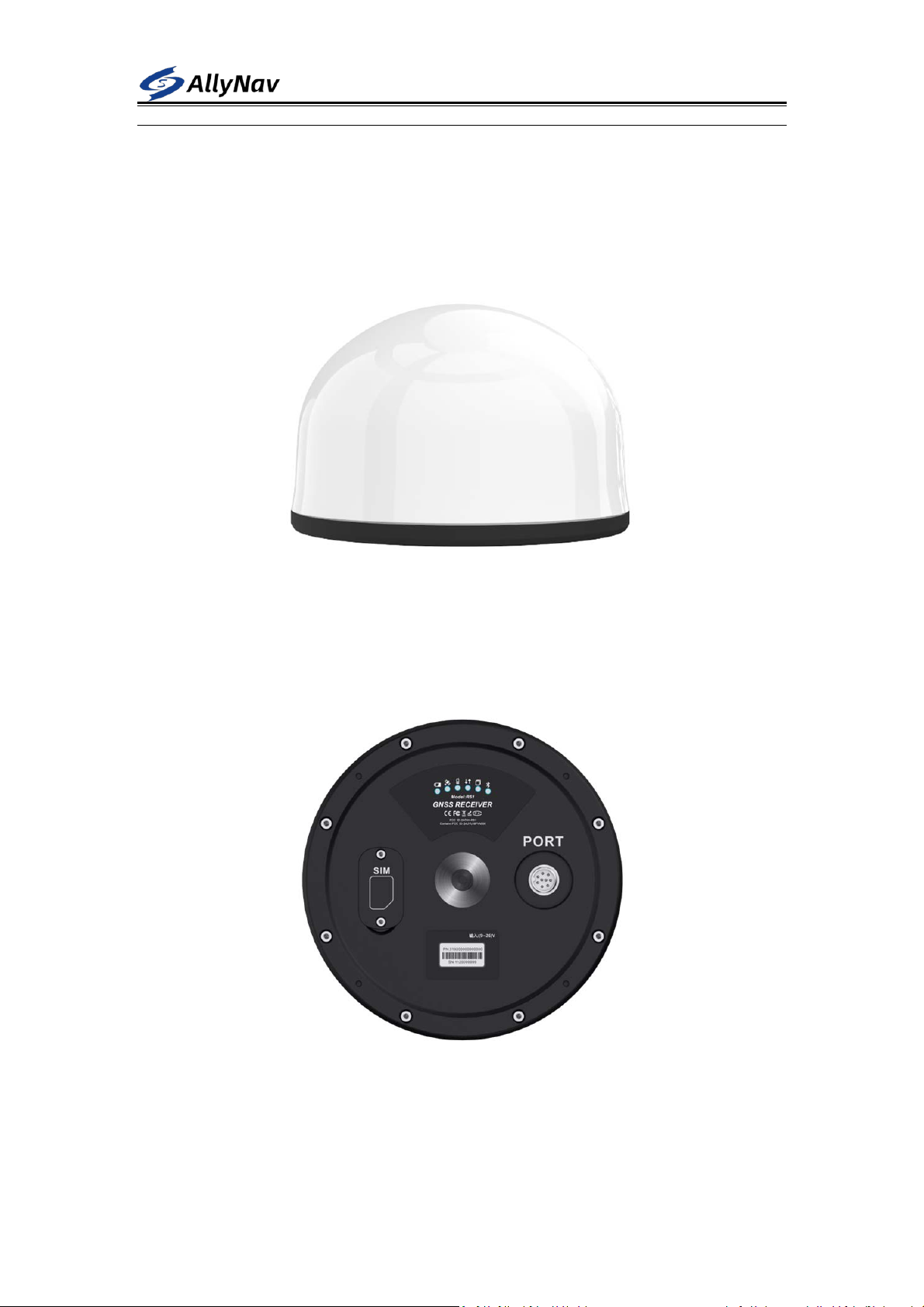
1.4 User
Interface
1.4.1 Front
1.4.1 Bottom panel
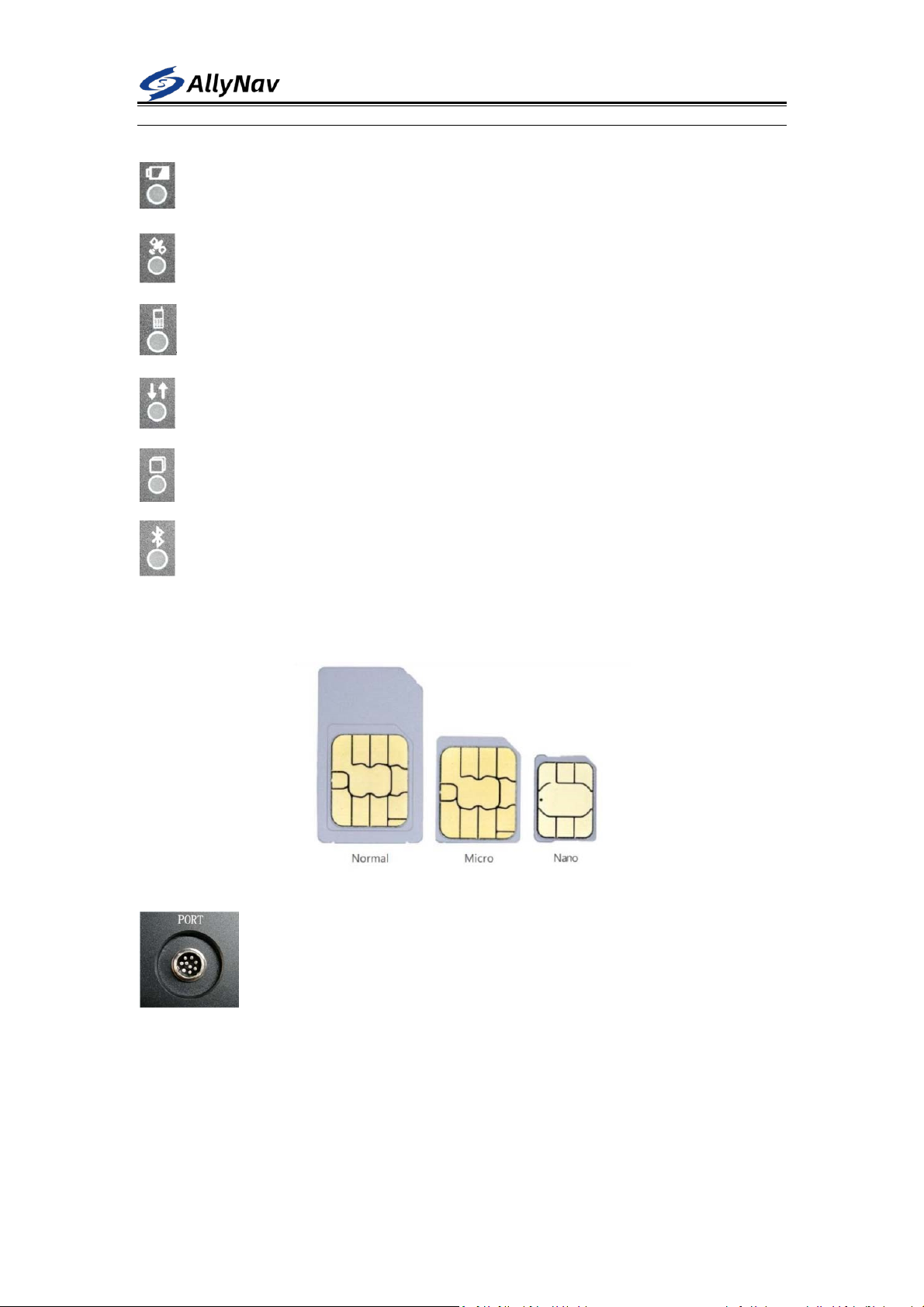
The bottom panel has a nine-pin aviation plug, 6 LED indicators , and a SIM card slot. In order to
achieve IP67 waterproof level, the SIM card baffle is fixed with 2 screws
S
HANGHAIALLYNAVTECHNOLOGYCO.,LTD
Power light: red and blue flash alternately when power on
Differential light red: (monitoring mode is disabled)
4G light red: 4G is not online, flashes every 5s , and flashes every 1s after going online.
Differential data status light red (monitoring mode is disabled)
Storage light red : (Monitoring mode is disabled)
bluetooth light is red : the bluetooth is not connected and flashes once for 3 s, and the
bluetooth flashes twice for 1 s after the bluetooth is connected.
SIM card : Use a NANO SIM card, with the chip facing down
PORT nine -pin aviation plug: used for 12V DC power input and one R S232
communication serial port.
SHANGHAIALLYNAVTECHNOLOGYCO.,LTD
1. 5 Accessories
This chapter provides accessory information. Before starting the installation, make sure
that all accessories used in the project meet specifications and standards.
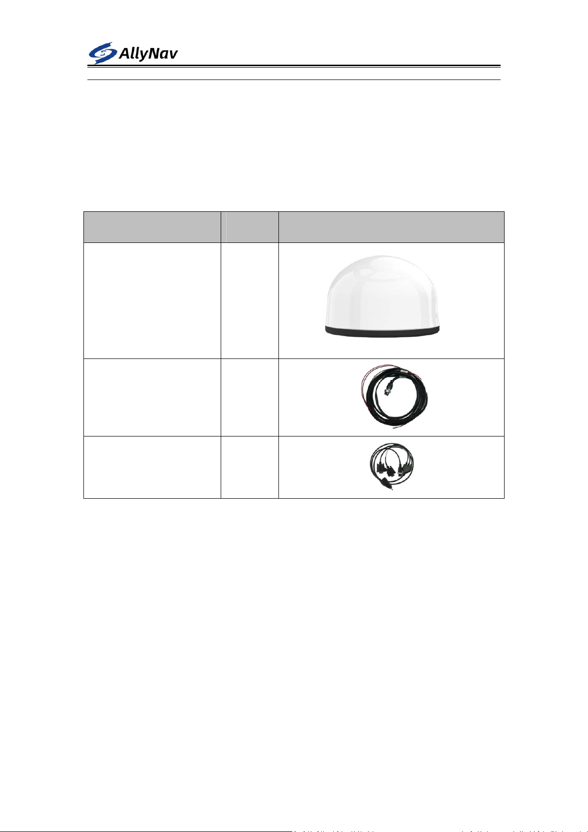
1.5.1 Configuration List
name quantity picture
R 51 Universal Receiver
(Host)
1 pcs
Nine core aviation plug power
cord
1 pcs
Nine core aerial plug setting
line
1pcs
1.5.2 Data line interface definition
nine -core aerial plug setting line mainly includes 1 DC power port, 2 R S232 serial ports
The nine-core aviation plug power cord includes a solar power supply interface and a
battery power supply interface
SHANGHAIALLYNAVTECHNOLOGYCO.,LTD
Defined as follows
R51 universal receiver P ORT nine-core aviation plug pin definition
Aviation PIN
sequence (male)
definition
1
POWER+
2
POWER -
3 SOLAR +
4 L E_AC BAT
5 R S232 RX
6 RS232TX _
7 G ND
8 G ND
9 P_ON _
Nine-core aerial plug power cord P IN pin definition
Aviation PIN
sequence (female)
definition
1 (empty )
2 (empty )
3
SOLAR + (Solar Anode)
4
B AT+ (battery positive)
5 (empty )
6 (empty )
7
SOLAR- (Solar Negative )
8
B AT- (battery negative
electrode)
9 (empty )
Nine-core aerial plug setting line P IN pin definition
Aviation PIN
sequence (female)
definition
1 DC 12V positive
2 D C 12V negative pole
3 COM RS232B
4 (empty )
5 C ONFIG RS232 B
6 C ONFIG RS232A
7
COM RS232A
8 (empty )
9 (empty )
PORT RS232: Various parameters of the receiver can be configured through the serial

SHANGHAIALLYNAVTECHNOLOGYCO.,LTD
port tool, the default baud rate is 115200 .
2 Overview of the configuration instruction set
System debugging instructions
S ET UART CONFIG Open system configuration
M ODE0 Switch to debug mode
M ODE1 Switch to monitoring work mode
C ONCOM12 Connect to G NSS board debug interface
C ONCOM13 Connect the gyroscope debugging interface
C ONCOM14 Connect 4G network module debugging interface
C ONCOM15 System debugging interface and Bluetooth transparent transmission
C ONCOM25 Transparent transmission between G NSS board and Bluetooth module
B ATTIME60 Set the time interval for uploading power information, once every 60
seconds; the setting range is 0 ~ 255 seconds
S AVE LIST
save system configuration
G NSS board debugging instructions
U NLOGALL Turn off all outputs of the G NSS board
L OG RANGEB ONTIME 1 Hz raw observation data in binary format
L OG RANGEA ONTIME 1 Output 1 Hz raw observation data in ASCII format
LOG GPSEPHEMB ONTIME 300 GPS ephemeris in binary format , every 300 seconds
LOG BD2EPHEMB ONTIME 300 DS ephemeris in binary format , every 300 seconds
LOG GLOEPHEMERISB
ONTIME 300
GLO ephemeris in binary format , every 300 seconds
LOG GPSEPHEMA ONTIME 300 Output GPS ephemeris in ASCII format , every 300 seconds
M ODE ROVER
Converting from Base Mode to Rover Mode
L OG GPGGA ONTIME 0.5 Output G PGGA statement 2 Hz
MASK 15 Set the satellite altitude cutoff angle to 15 degrees
SAVECONFIG Save the board configuration
Gyro debugging instructions
41 6C 6C 79 02 FF AA 03 03 00 Modify the output frequency of the gyroscope with ID number 0 2 to 1 Hz
(H EX send )
41 6C 6C 79 02 FF AA 0 4 0 6 00 Modify the baud rate of the gyroscope serial port with ID number 0 2 to
115200 (sent by H EX )
41 6C 6C 79 02 FF AA 2D FF 00 Modify the ID number of the gyroscope whose ID number is 0 2 to FF ;
allow the modification range of 0 0 ~ FF (H EX send)
4G network debugging instructions
SETG3CONFIG _ Turn on 4G configuration state
SETG3MODE0 _ 4 G module switches to debug mode
SETG3IP0192.168.1.100 _ Set the TCP server IP to 1 92.168.1.100
Indice
Altri manuali AllyNav Strumento di misura


