925-0417 REV A 5 0124
BMRX-300 DC Rotary Level Indicator
INTRODUCTION
1.0 INTRODUCTION
The BinMaster BMRX-300 is a rotary level sensor that provides reliable point level detection
in bulk solids, including powder, pellet, and granular materials. The unit's status is continually
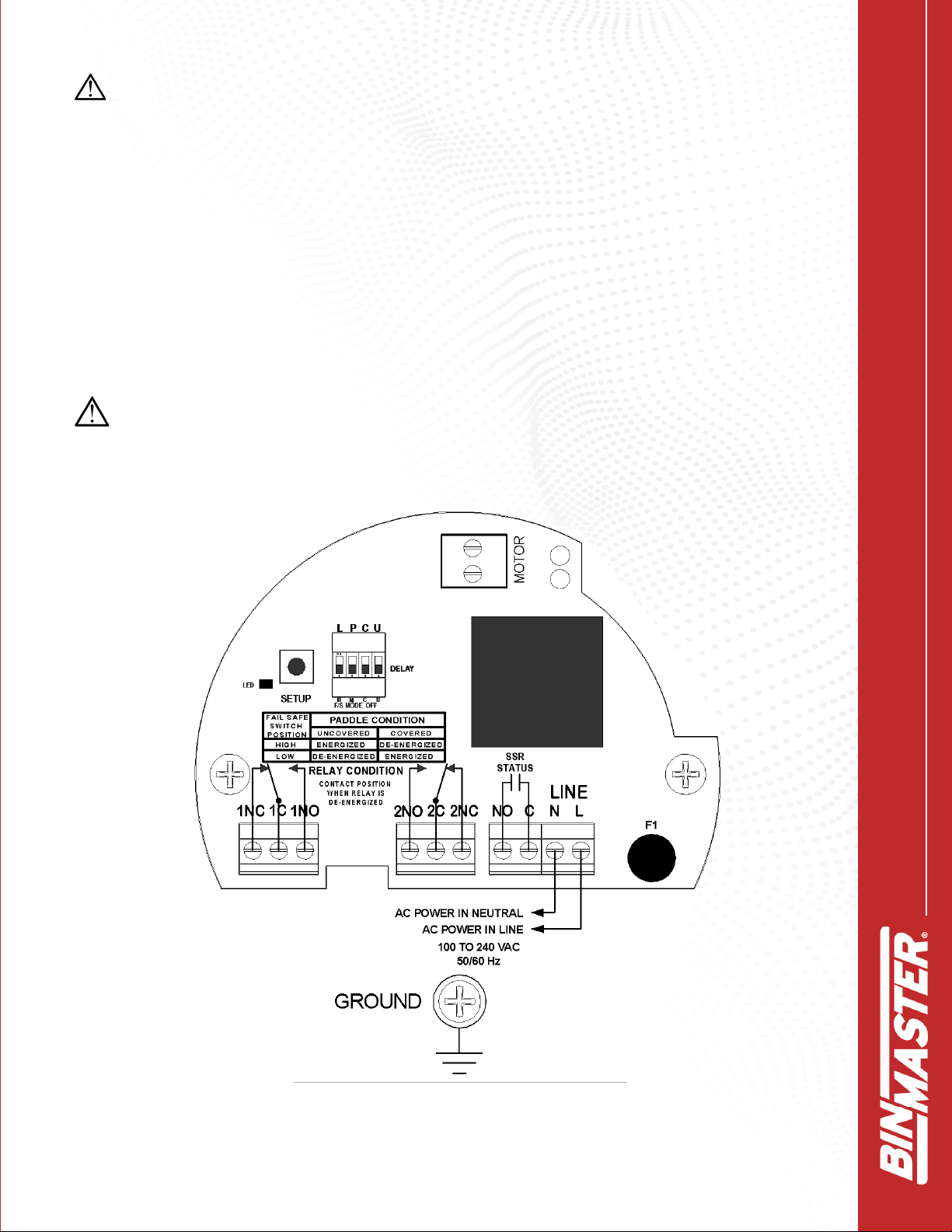
monitored, and its fail-safe circuitry will fail to a "safe" condition on the event of a failure or power
failure. A visual LED array continually indicated the sensors status, giving a quick visual of paddle
rotation, covered condition or fault condition. A status relay output is also provided for external
monitoring of the sensor status.
The BMRX-300 motor rotates the drive shaft and paddle at 1 RPM. When the material lls to the
level of the indicator paddle, it causes the paddle to stop rotating indicating a covered condition.
When the material falls away, the paddle resumes rotating to indicate an uncovered condition.
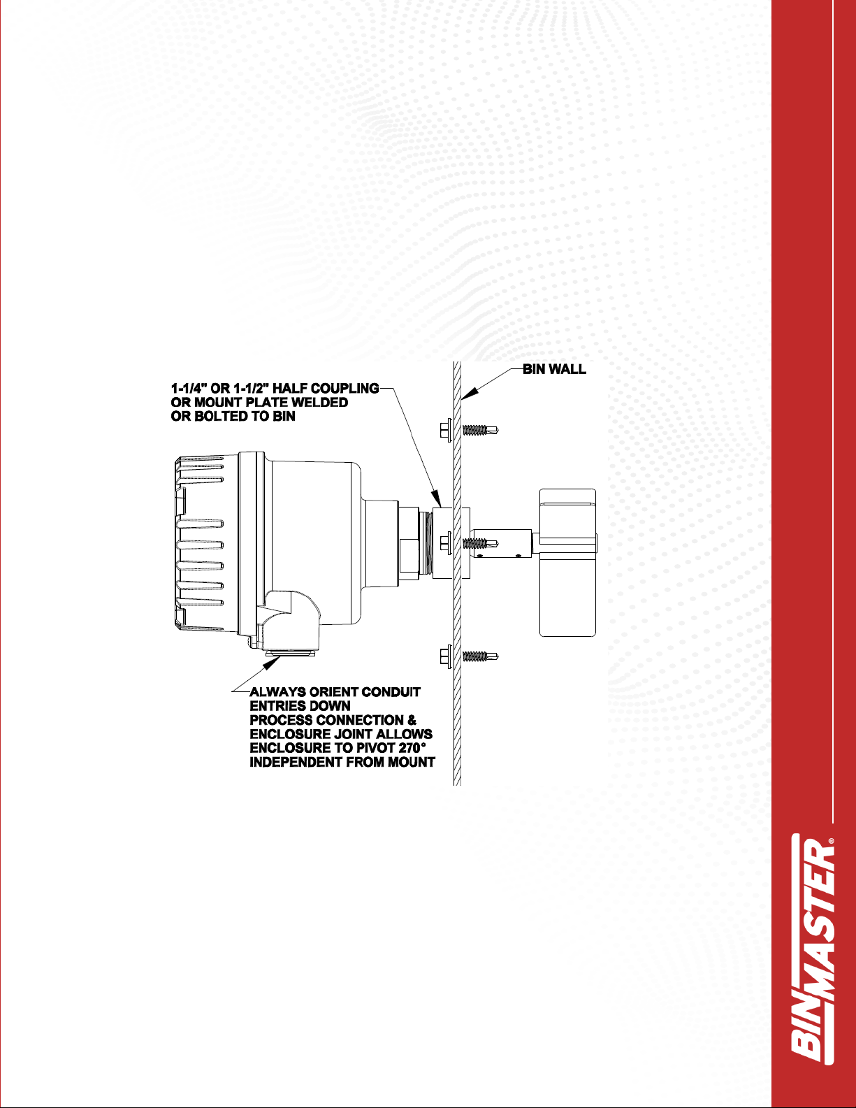
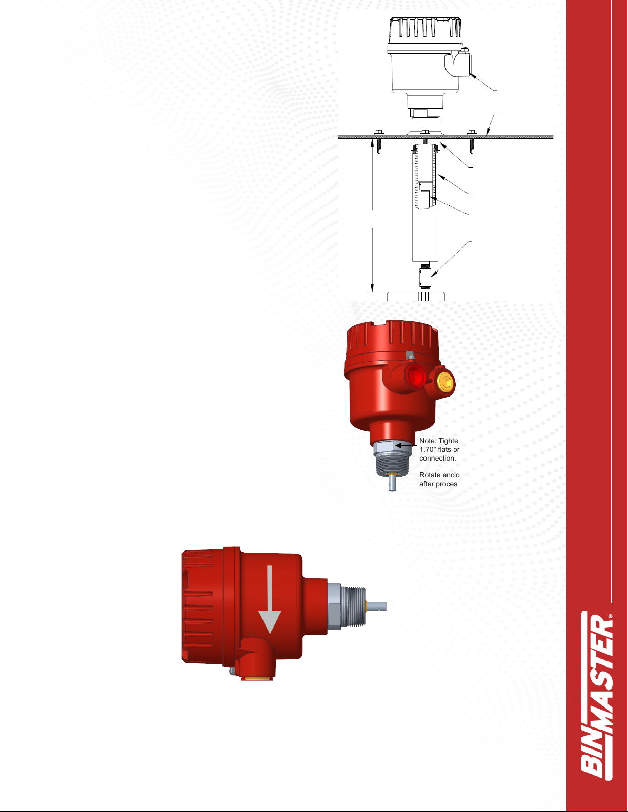
2.0 INSTALLATION
2.1 Mounting Summary
The BMRX-300 has three optional process ttings available to mount the indicator; 1.25” NPT,
1.5” NPT, or 1.5” tri-clover tting. The BMRX-300 can be mounted using a mounting plate, welded
in couplings, or mating the tri-clover tting with a anged end with an internal diameter big enough
for the paddle to t through.
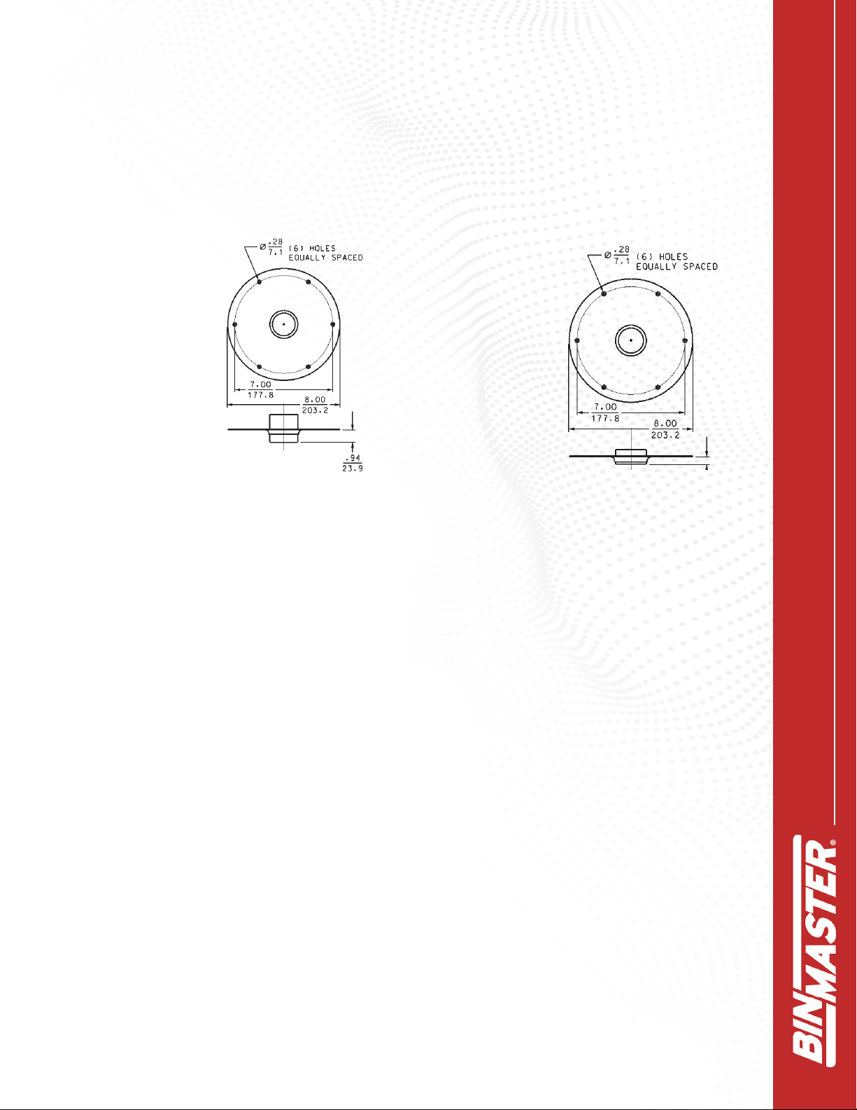
Mounting Plates
Mounting plates allow installing a completely assembled rotary through the vessel side or top.
The mounting plates have 6 bolt holes equally spaced on a 7-inch bolt circle. Mounting plates are
available with 1.25” or 1.5” NPT half or full couplings dependent on the process tting size of the
rotary.
Half couplings are used for all side mount installations or if top mounting a rotary without using a
guard pipe.
Full couplings are for top-of-vessel installations when using shaft extensions and shaft guard
pipes. Do NOT use full couplings for side mounting. The void on the process side of a full coupling
could allow material to pack in the void and interfere with rotation of the rotary shaft.
Cut a hole in the vessel wall large enough for the paddle to t through. Place the gasket between
the mounting plate and the vessel and install 6 mounting bolts through the mounting holes to
secure the plate to the vessel.
Mounting without Mounting Plates
Select a coupling or tri-clover tting that matches the size of the process tting on the rotary. Cut a
hole in the vessel big enough to t the coupling through the vessel wall. Weld the coupling to the
vessel wall to seal out moisture and dust.