BOQU SD Series Manuale utente

SD Series Online Color Meter
OPERATING INSTRUCTIONS
Content
1. Introduction…………………………………………………… 1
2. Product name and model description……………………… 1
3. Technical parameters……………………………………… 2
4. Measuring principle………………………………………… 3
5. Structural features…………………………………………… 3
6. Installation wiring…………………………………………… 3
7. Panel operating instructions………………………………… 5
8. Routine maintenance……………………………………… 12
9. Matters needing attention…………………………….. …. 13
Operating instructions for SD Series Online Color Meter
1
1. Introduction
Dear users:
Thank you for choosing the SD Series Online Color Meter
developed by our company ,To ensure correct and efficient use of
the instrument, please read this manual thoroughly and fully
understand how to operate the instrument before operating it。
SD Series Pipeline Online Color Meter,Pipeline type totally
enclosed detection to Avoid external light interference,Reliable
and accurate measurement,Can be widely used in Chromaticity
monitoring of sewage enterprises ;Municipal pipe network
monitoring ;Industrial process chroma monitoring ,Effluent
monitoring of printing and dyeing plant,Chemical effluent, etc。
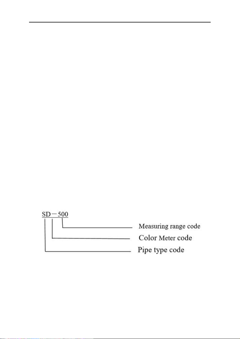
1. Product name and model description
Product name:Online Color Meter
Model:SD Series
2. Technical parameters
Range:SD-500 0.1-500.0PCU
Resolving power:0.1 与1PCU
Response time:Quick response

Operating instructions for SD Series Online Color Meter
2
Storage time:>3 years
Recording interval: 0-30 Minutes can be setup,Default 10
minutes
Display mode:LCD and Key
Cleaning method: Manual cleaning(Cleaning method and
Matters needing attention ,Please refer to the following
chapter)
Sample flow rate:0mL~3000mL/min,Ensure that the flow
rate is no bubbles
Working temperature:0~55℃
Analog output:4~20mA output(Four wire system ,No need
to provide 24V)
Relay output:Four SPDT,230VAC,5A;
Fault alarm: two Acousto-optic alarm, Display prompt,
Alarm value and time can be set
Power Supply:AC,100~230V,50/60Hz or 24VDC ;power
50W
Inflow pipeline:1/4" NPT,(Provide external interface)
Outflow pipeline:1/4" NPT,(Provide external interface)
Digital communication:MODBUS/RS485, Communication
speed and station address can be setup
Standard method:National standard
Size:40×33×10cm
Weight: 3Kg
Operating instructions for SD Series Online Color Meter
3
3. Measuring principle
This module monitors by Constant incident light Irradiated
on liquid surface,The receiving chip will dynamically measure
the chroma of water 。If the water is turbid, it may affect the
measurement accuracy ,It is recommended to filter and clean
before entering water。
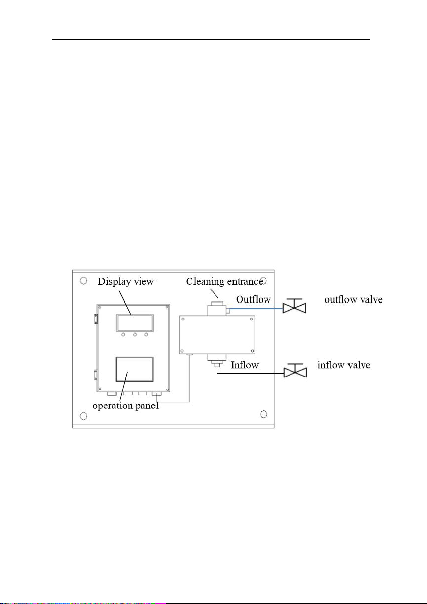
4. Structural features
Outline structure and installation instructions of Online Color Meter,
As shown in the figure below。
Careful:
1. Outflow valve flow control to minimum,
It must be
less than the inflow flow ,Let the measuring tube
have a certain air pressure,Otherwise, there will be
bubbles,Influence measurement value
2. Panels should be installed vertically
Operating instructions for SD Series Online Color Meter
4
5. Installation wiring
6.1.Instrument installation
The instrument shall be installed in a clean, dry, well
ventilated place without vibration。
1.There are 4 studs on the bottom plate for installation。
2.Interface between measurement and water sample
collection 1/4" NPT Internal thread ,You can also choose card
sleeve installation.。
Influent mode:
Down in and up out,
Keep the inflow
valve as small as possible,The best way is that water
does not produce bubbles。
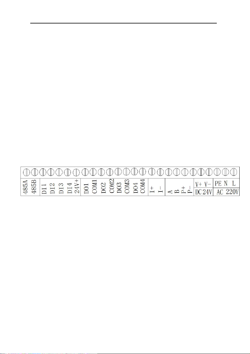
6. 2. Connection mode
L: 220AC
N:220AC
PE: Earthing
V+,V-:DC 24V input
A,B,P+,P-:Communication wiring with front end(A:
Green wire,
B:
Black wire,
P+:
Red wire,
P-:
Yellow wire)
I+:4-20mA+ output(Four wire system current positive, No
need to provide 24V)
I-:4-20mA- (Four wire system current negative, No need
to provide 24V)
DO1,com1:Alarm1 relay action
DO2,com2:Alarm2 relay action
DO3,com3:unuse
Operating instructions for SD Series Online Color Meter
5
DO4,com4:unuse
DI1-DI4:unuse
485A,485B:MODBUS communication interface
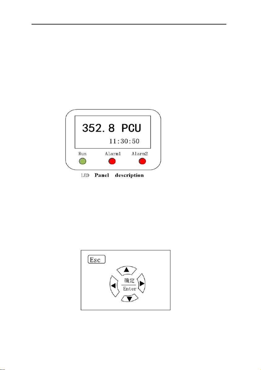
6. Panel operating instructions
6.1. Instrument panel and operating instructions
1.Real time display of current chroma value;
2.Alarm light display;
3.Real time clock display;
4.Run LED is normal operation;
5.Alarm1 Led is low alarm;
6.Alarm2 led is high alarm;
Operation panel description
1.▲Indicates move up or value increase key(Up key)
Operating instructions for SD Series Online Color Meter
6
2.▼ Indicates move down or value decrease key(Down key)
3.◄ Indicates move Left(Left key)
4.► Indicates move Right(Right key)
5. ENTER: Acknowledgement key
6.ESC: Return or exit key(Go back to the previous menu)
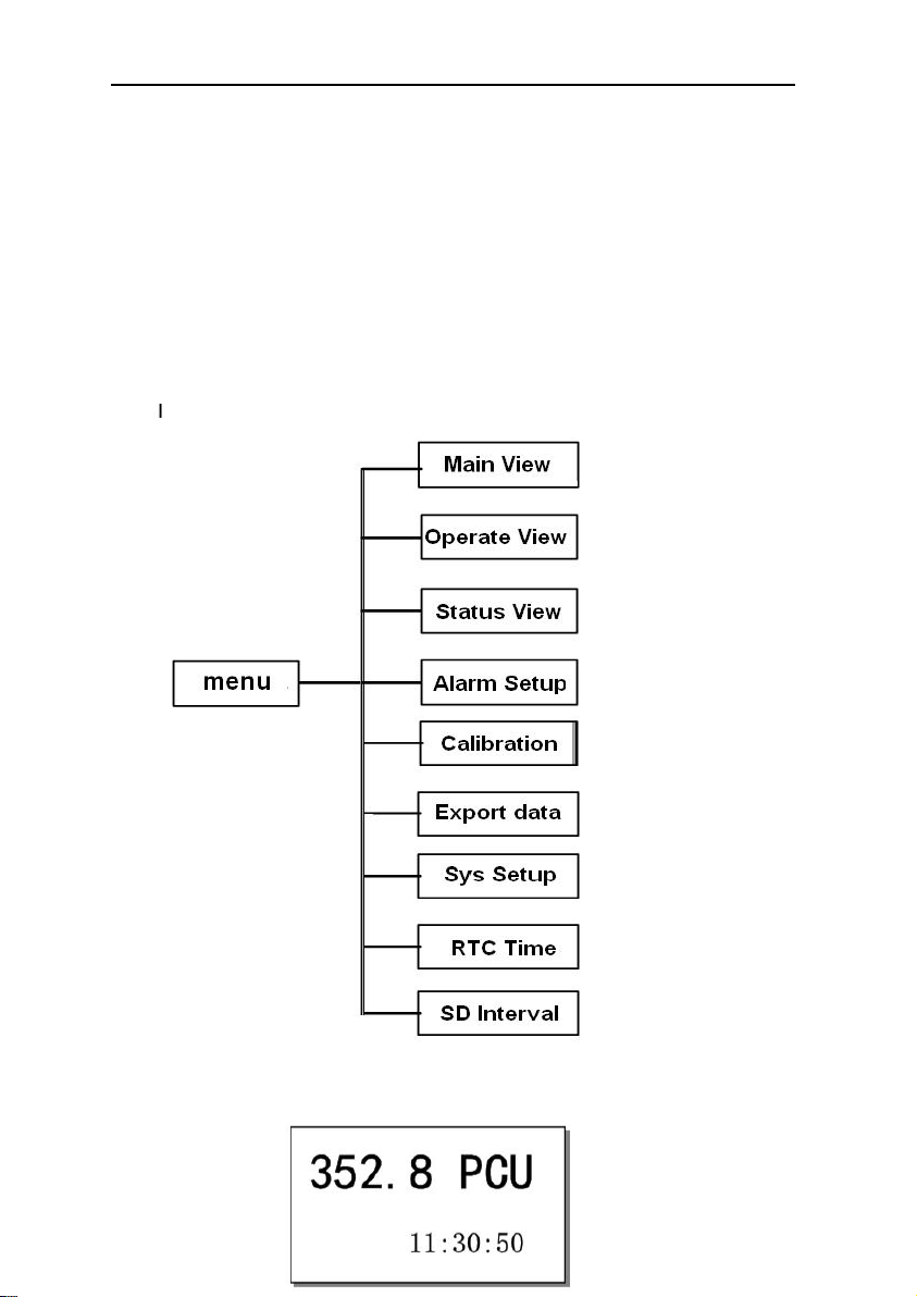
6.2. Menu
7.3.Main interface and main menu
Operating instructions for SD Series Online Color Meter
7
Chroma value is mainly displayed in the main interface,If
chroma value greater than set value, The alarm led red light up.
When the view is displayed as the main view,
Press the ESC
key,Can get into Function menu page。As shown in the figure
below:
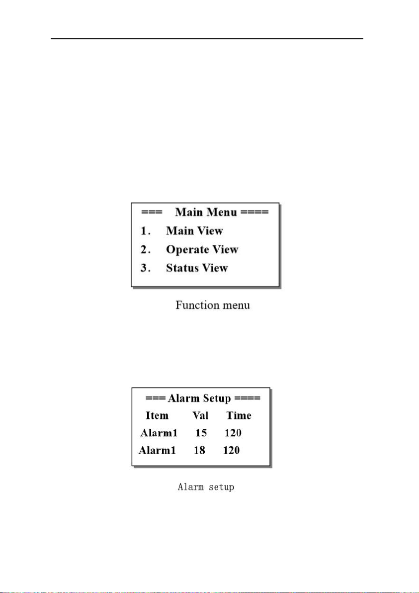
Press up key or down key to move options,Press ENTER key
to enter the corresponding option。
7.4. Alarm settings
Alarm setting view is mainly used to set the alarm value
and alarm time of chroma alarm 1 and alarm 2。
careful:If you do not press enter after setting,Set
value not saved。
Operating instructions for SD Series Online Color Meter
8
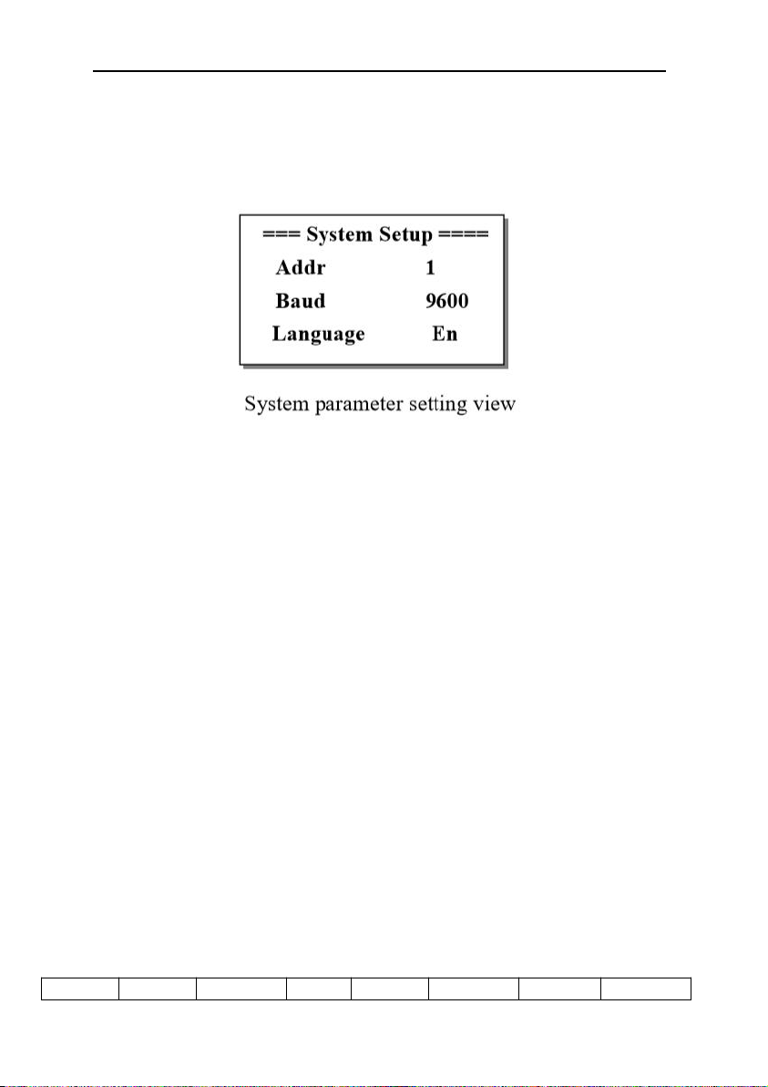
7.5. System setup
In this view, you can select the address of Modbus
communication station(1-32),communication rate and language。
The system defaults station is no 1,Communication baud rate is
9600Bps,Language is Chinese。
Communication data format:One start bit, eight data bits, one
check bit and one stop bit。
Verification method: CRC check.
Broadcast information is not supported。
Upload data mode,Implement with 03 command,It can transmit
the switching value (in word form) and analog value in the
Numerical controller,The specific process is as follows。
For example :Read the analog down transfer register with the
starting address of 0000H, with the length of 09 words
03 Command request message:
address
function
Data start
Data
Data
Data
CRC
CRC
Operating instructions for SD Series Online Color Meter
9
register
high
start
registe
r low
length
high
length low
check
code low
check
code high
02
03
00
00
00
09
03 Command response message:
Communication data address definition
address
Data name
Data definition
type
Explai
n
Remarks
000.0
Data name
000.1
003.3
Alarm 1
1 Alarm
bool
003.4
Alarm 2
2 Alarm
bool
0006
Chroma
value
0-1000 对应 0-100.0
int
0007
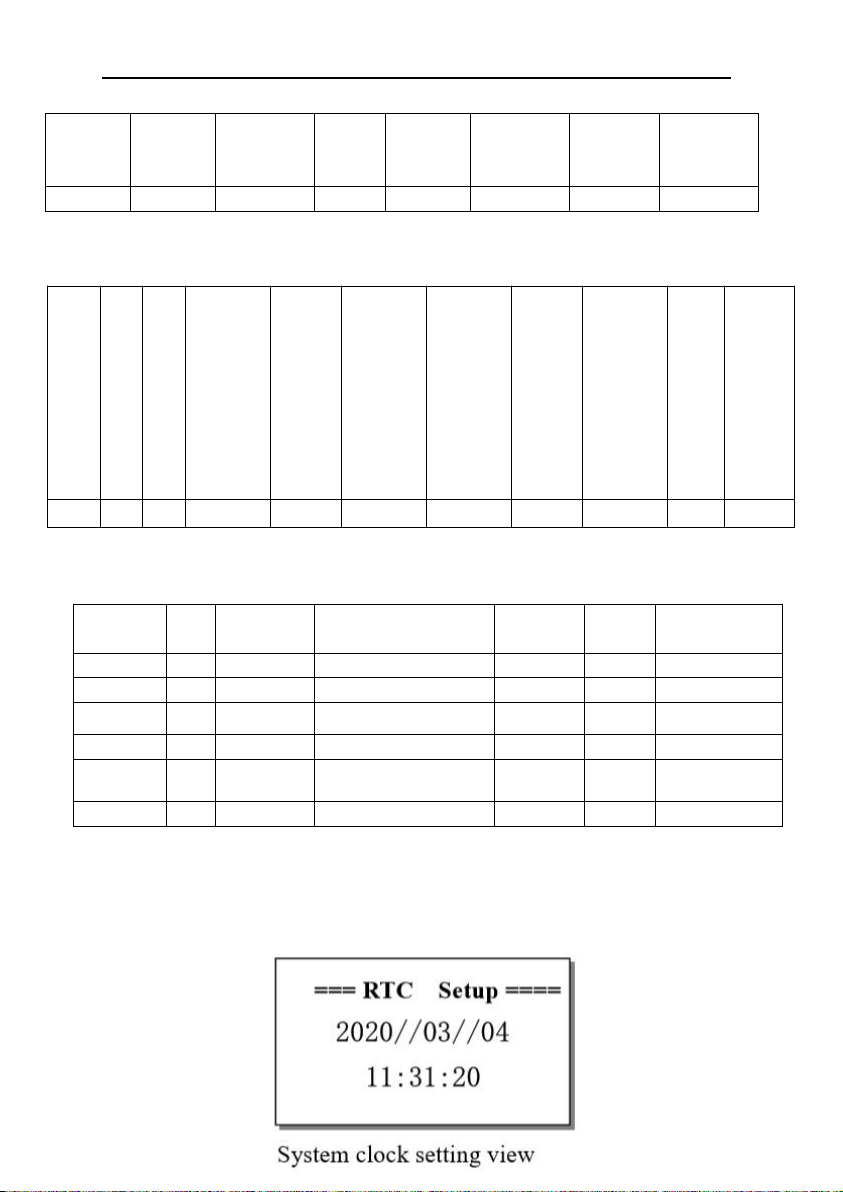
7.6.Clock setting
address
function
Bytes
High bit of data output
register0014
Low bit of data output
register0014
High bit of data output
register……
Data output register low
……
High bit of data output
register0027
Data output register low
0027
CRC check code low
CRC check code high
02
03
28
01
2B
00
00
00
64
Indice
Altri manuali BOQU Strumento di misura


