CYP CH-331H-RX Manuale utente


DISCLAIMERS
The information in this manual has been carefully checked and
is believed to be accurate. Cypress Technology assumes no
responsibility for any infringements of patents or other rights of third
parties which may result from its use.
Cypress Technology assumes no responsibility for any inaccuracies
that may be contained in this document. Cypress also makes no
commitment to update or to keep current the information contained
in this document.
Cypress Technology reserves the right to make improvements to this
document and/or product at any time and without notice.
COPYRIGHT NOTICE
No part of this document may be reproduced, transmitted,
transcribed, stored in a retrieval system, or any of its part translated
into any language or computer le, in any form or by any means—
electronic, mechanical, magnetic, optical, chemical, manual, or
otherwise—without express written permission and consent from
Cypress Technology.
© Copyright 2018 by Cypress Technology.
All Rights Reserved.
TRADEMARK ACKNOWLEDGMENTS
All products or service names mentioned in this document are
trademarks of the companies with which they are associated.

SAFETY PRECAUTIONS
Please read all instructions before attempting to unpack, install or
operate this equipment and before connecting the power supply.
Please keep the following in mind as you unpack and install this
equipment:
• Always follow basic safety precautions to reduce the risk of re,
electrical shock and injury to persons.
• To prevent re or shock hazard, do not expose the unit to rain,
moisture or install this product near water.
• Never spill liquid of any kind on or into this product.
• Never push an object of any kind into this product through any
openings or empty slots in the unit, as you may damage parts
inside the unit.
• Do not attach the power supply cabling to building surfaces.
• Use only the supplied power supply unit (PSU). Do not use the PSU
if it is damaged.
• Do not allow anything to rest on the power cabling or allow any
weight to be placed upon it or any person walk on it.
• To protect the unit from overheating, do not block any vents or
openings in the unit housing that provide ventilation and allow for
sufcient space for air to circulate around the unit.
• Please completely disconnect the power when the unit is not in
use to avoid wasting electricity.
VERSION HISTORY
REV. DATE SUMMARY OF CHANGE
VS1 2019/01/28 Final technical review
VS2 2019/01/31 Updated Section 1, 5

CONTENTS
1. Introduction......................................................1
2. Applications.....................................................1
3. Package Contents ..........................................1
4. System Requirements......................................2
5. Features............................................................2
6. Operation Controls and Functions.................3
6.1 Front Panel................................................. 3
6.2 Rear Panel.................................................. 4
6.3 IR Cable Pinouts ........................................ 5
6.4 Serial Port Pinout and Defaults ................ 5
6.5 WebGUI Control........................................ 6
6.5.1 System Tab........................................ 7
6.5.2 Video Wall Tab............................... 10
6.5.3 Network Tab ................................... 14
6.5.4 Functions Tab ................................. 17
6.6 Telnet Control.......................................... 19
6.7 Telnet Commands................................... 20
6.7.1 System Commands........................ 20
6.7.2 Network Commands..................... 21
6.7.3 Discovery Service Commands..... 22
6.7.4 Receiver Specic Commands...... 23
6.7.5 Serial Commands........................... 28
7. Connection Diagram ....................................30
8. Specications ................................................31
8.1 Basic Specications ................................ 31
8.2 Video Specications............................... 32
8.3 Audio Specications............................... 33
8.4 Cable Specications .............................. 34
9. Acronyms.......................................................35

1
1. INTRODUCTION
This unit is an HDMI over IP Receiver that allows you to receive
extended HDMI signals using the TCP/IP protocol over regular Cat.5e
network cable. This extender supports the reception of High-Denition
signals (up to 1080p@60Hz) with audio up to 100m over a single cable.
The distance can be further extended (up to 100m per segment) by
using Gigabit Ethernet network switches, allowing the user to cascade
the system without signal loss or introducing delay. This Receiver also
features bi-directional IR and RS-232 pass-through.
It is also possible to for this Receiver to operate in multicast mode,
allowing large groups of Receivers within the same local network
to receive the same AV signal with no additional bandwidth cost.
Additionally, that same multicast signal can be used to create large
multi-display video walls with amazing simplicity.
This Video over IP system is perfect for both residential and commercial
installation environments. Conguration information is provided via
the On-Screen Display (OSD) when the unit is unlinked and control
is via front panel buttons, WebGUI, Telnet, or the AV over IP Master
Controller.
2. APPLICATIONS
• HDMI, IR, and RS-232 extension
• Hotel or convention center display multi-monitor broadcast
• Long distance data and video transmission via cascading
• Distributed video matrix system
• Distributed video wall system
3. PACKAGE CONTENTS
• 1×HDMI over IP Receiver
• 1×5V/2.6A DC Power Adapter
• 1×3.5mm to IR Extender Cable
• 1×3.5mm to IR Blaster Cable
• 1×3.5mm to DE-9 Female Adapter Cable
• 1×Shockproof Feet (Set of 4)

2
• 1×Operation Manual
4. SYSTEM REQUIREMENTS
• HDMI receiving equipment such as an HDTV, monitor or audio
amplier.
• A compatible HDMI over IP Transmitter is required.
• A Gigabit Ethernet network switch with jumbo frame support is
required for multi-endpoint extension. (8K jumbo frames are strongly
recommended.)
• A Gigabit Ethernet switch with “IGMP snooping” enabled is required
for multicast support.
• A managed Gigabit Ethernet switch with VLAN support is strongly
recommended.
Special Notes:
• Mostconsumer-graderoutersarenotabletohandlethehightrafc
rates generated by multicast mode, so using one as your VoIP
network switch is discouraged.
• AvoidmixingregularnetworktrafcwithVoIPtrafc.Ifphysically
separatingthenetworkisnotpossible,VoIPtrafcshouldreside
within its own subnet or VLAN.
5. FEATURES
• HDMI 1.4 and DVI 1.0 compliant
• HDCP 1.4 compliant
• 1 HDMI output
• Video, audio and control reception over TCP/IP in Unicast (point- to-
point) or Multicast (single-to-many) modes
• Multi-monitor video wall support with 180° and 270° rotation options
• Video output can be scaled to a selected resolution, or left
unscaled
• HDMI output supports resolutions up to 1080p@60Hz/WUXGA
• Supports pass-through of audio formats including LPCM 2.0/5.1/7.1,
Bitstream and HD Bitstream
• Supports IR and RS-232 bypass

3
• Unit has an info OSD (when unlinked) and can be controlled via
front panel buttons, WebGUI, Telnet, and the AV over IP Master
Controller
6. OPERATION CONTROLS AND FUNCTIONS
6.1 Front Panel
POWER RESET
LINK
ISP ISP
ON OFF
LINK MODE
CH - CH +
3 4 51 2
1POWER LED: This LED will ash while the unit is powering on and will
illuminate solidly once it has nished booting and is ready for use.
LINK LED: If the unit has no network connection this LED will not
illuminate. While the unit is attempting to establish a connection
with a Transmitter this LED will ash. When the unit has established a
stable connection with a Transmitter this LED will illuminate solidly.
2RESET Pinhole: Press this recessed button with a paperclip tip to
reboot the unit.
Note: Settings will not be reset.
ISP Pinhole: For factory use only.
3ISP Switch: For factory use only. For normal operation, this switch
should be set to “OFF”.
4 LINK/CH− Button: This button controls multiple functions:
A Channel −: Press this button momentarily to decrease the
streaming channel to the previous available channel on the
local network.
Note: If no other channels are detected, the channel number
will not change.
BVideo Link: Press and hold the button for 3 seconds to enable
or disable the Video Link. When the link is disabled and the
Receiver is connected to a display it will show the system’s
current IP and rmware information.
5 MODE/CH+ Button: This button controls multiple functions:

4
AChannel +: Press this button momentarily to increase the
streaming channel to the next available channel on the local
network.
Note: If no other channels are detected, the channel number
will not change.
BMODE: Press this button momentarily to toggle the video data
streaming method between “Graphic” and “Video” modes.
“Graphic” mode is optimized for high-detail static displays and
“Video” mode is optimized for full motion video.
Note: Pressing and holding the MODE button while the unit is
powering on will perform a full factory reset on the unit. Once
theresetiscomplete,bothLEDswillashrapidlyandtheunit
must then be manually power cycled.
6.2 Rear Panel
DC 5V
LANIN OUT
IR
RS-232HDMI OUT
1 2 3 4 5 6
1HDMI OUT Port: Connect to an HDMI TV, monitor, or amplier for
digital video and audio output.
2RS-232 Port: Connect to a PC, laptop, or serial controllable device
for the extension of RS-232 signals. The baud rate is congurable,
but the default baud rate is 115200.
Note: When a Transmitter is in multicast mode, every connected
Receiver unit can send RS-232 commands to that Transmitter
and commands sent from the Transmitter side will be sent to all
associated Receivers.
3IR IN Port: Connect to an IR Extender to receive IR control signals
and extend them to devices connected to the Transmitter on the
same broadcast channel. Ensure that the remote being used is
within direct line-of-sight of the IR Extender.
4IR OUT Port: Connect to the provided IR Blaster to transmit IR signals
from the Transmitter on the same broadcast channel to devices
within direct line-of-sight of the IR Blaster.
5
Note: When the Transmitter is in multicast mode the IR signal is sent
to all associated Receivers.
5LAN Port: Connect to a Gigabit Ethernet switch for signal extension
from a compatible Transmitter, and to allow WebGUI/Telnet
control.
6DC 5V Port: Plug the 5V DC power adapter into this port and
connect it to an AC wall outlet for power.
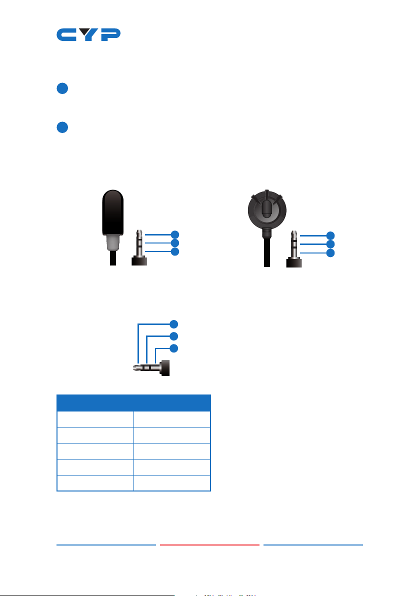
6.3 IR Cable Pinouts
IR Blaster
Cabl
e
1
2
3
Infrared
Power
Not U
sed
IR Extender
Cabl
e
1
2
3
Infr
ared
Power
Ground
6.4 Serial Port Pinout and Defaults
3.5mm to DE-9
A
dapter Cable
RxD
TxD
GND
1
2
3
Serial Port Default Settings
Baud Rate 115200
Data Bits 8
Parity Bits None
Stop Bits 1
Flow Control None
Indice
Altri manuali CYP Ricevitore

CYP
CYP PRO-HDMIFO-KIT Manuale utente

CYP
CYP COH-TX1 Manuale utente

CYP
CYP IP-A750RX Manuale utente

CYP
CYP PRO-F21RX Manuale utente

CYP
CYP CH-517RXHS Manuale utente

CYP
CYP CSC-6012TX Manuale utente

CYP
CYP PUV-1830RX-AVLC Manuale utente

CYP
CYP CH-2527TXV Manuale utente

CYP
CYP RXWPBD Manuale utente

CYP
CYP CH-352RX Manuale utente

CYP
CYP HDMI Over CAT5 Manuale utente

CYP
CYP CA-USBST Manuale utente

CYP
CYP CDVI-301TX & RX Manuale utente

CYP
CYP CH-1604TXD Manuale utente

CYP
CYP CH-2538TXWPKD Manuale utente

CYP
CYP AVIP-P5104R-B1C Manuale utente

CYP
CYP AVX-101F-RX Manuale utente

CYP
CYP 5-Play HDBaseT PU-507WPRX Manuale utente

CYP
CYP PUV-2100RX-AVLC Manuale utente

CYP
CYP PU-607BD-RX Manuale utente


