HandyTrac Touch Istruzioni operative originali

HandyTrac Touch
Key Control System
SystemSystem
InstallationInstallation
&&
OperationOperation
GuideGuide
© HandyTrac Systems. All Rights Reserved.Handytrac.com service@handytrac.com
HARDWARE INSTALLATION
New System Setup...........................................................
Customer Supplied Hardware....................................
Cabinet Mounting & Alignment ...............................
Mounting System ............................................................
Double Cabinet Setup ..................................................
Key Panels ..........................................................................
POWER AND NETWORK SET UP
System Power ...................................................................
Establishing Communications ..................................
Connecting Using Wireless Connection ..............
INITIAL SETUP
Website Access ..............................................................
The Key Map ....................................................................
Adding & Removing Badges ....................................
Programming Fingerprints .......................................
SYSTEM USAGE
Pulling a Key .....................................................................
Returning a Key ..............................................................
Changing Apt/Unit# ....................................................
Editing Key Tags .............................................................
Website Features ...........................................................
Vendor Key Receipts ...................................................
12
13
14
15
18
20
24
25
27
33
8
9
10
2
3
4
5
6
7

HandyTrac Touch
User Guide
2
New System Setup
Congratulations on the purchase of your new
HandyTrac Touch Key Control System! This guide includes
installation and usage information for both the HandyTrac
Touch Premium and HandyTrac Touch Standard Key Control
systems.
If you have any questions regarding this process, please
contact a HandyTrac technician at 888-458-9994 or email
service@handytrac.com.
Your system includes:
Touch system (Premium pictured) Panels with assigned Keytags Cabinet(s)
Setup package includes: 1) Key Map 2) Spare Keytags
3) Master Badge 4) Installation and Operation Guide
Backup Cabinet Keys
(Taped to back of
cabinet)

HandyTrac Touch
User Guide
3
Customer Supplied Hardware
Tools Needed
Internet Connection
1. Uninterruptible Power Supply (UPS)
- Minimum rating of 450VA. Required as part system warranty. Provides surge
protection and backup battery power.
2. Mounting fasteners
- Minimum 50 lbs load capacity for masonry, drywall, wood or metal studs.
1. Drill & Drill bits
2. Level
3. Flat head screwdriver
4. Phillips head screwdriver
5. Pliers
Available Options
1. WiFi 2.4 GHz (WPA/WPA2, WEP, 802.1x EAP)
(5 GHz networks are not supported)
OR
2. Wired Ethernet
(CAT5e ethernet cable not included)

HandyTrac Touch
User Guide
4
1. Mount the cabinet on the wall.
2. Mount the HandyTrac Touch system keypad on the
wall beside the cabinet.
3. Install second cabinet (if applicable)
4. Insert key panels in the cabinet(s).
• Use metal or plastic for shimming. Wood and rubber do not hold their shape well.
• If the door gap at top is greater than bottom, shim the top of the cabinet at right hand
corner.
• If the door gap on the bottom is greater than the gap on the top, shim the bottom of
the cabinet at the right hand corner.
Cabinet Alignment
Do not place the
manual backup keys
inside the cabinet.
Check the gap between door and door frame on all sides. If the gap is not uniform all
the way around, the cabinet will have to be shimmed to compensate for the uneven wall
surface.
Familiarize yourself with these steps before you get started.
The basic installation order is as follows:
1. To achieve the recommended height, stack the system
shipping box on top of the key cabinet shipping box.
This will give you a platform 44” high.
2. Place the cabinet on top of the boxes, then place a
level on top of the cabinet.
3. We strongly recommend attaching the cabinet to a
stud. Align at least one (1) stud with one of the six (6)
drilled mounting holes at the top of the cabinet.
4. Use a pencil to mark your holes. A minimum of nine
(9) screws are required for mounting the cabinet to
ensure proper plumb, squareness, and stiffness.
5. When all holes are marked, use screws that penetrate
at least two (2) inches into the stud or wall that are
capable of holding at least 50 lbs. Follow the
manufacturer’s directions for all anchors.
6. Lift the cabinet into place and tighten all fasteners
snug, but not fully. Place your level on top of the
cabinet and check repeatedly as you tighten all of the
fasteners.
Mount the Cabinet
Minimum
9 screws
required

HandyTrac Touch
User Guide
5
Mount the HandyTrac Touch
1. Hold the Touch keypad ush against the
side of the cabinet. The Electronic Lock
port on the side of the cabinet must be
aligned with the electronic lock cables from
the keypad.
2. Before mounting the keypad, gently feed
the electronic lock cables through the
electronic lock cable port on the right
side of the key cabinet. Make sure all three
cables are in good condition. Fasten the
keypad to the wall with your mounting
hardware.
3. Connect the electronic lock, light, and
switch connectors inside the key cabinet.
The ends of each connector are labeled.
4. Push extra cable lengths inside the main
Touch console and snap the cables into the
retaining clips on the inside of the cabinet.
This prevents contact with the key panels
during operation and protects the cables.
*wire colors may vary

HandyTrac Touch
User Guide
6
Installation of Second Cabinet (if applicable)
Install the included spacer on the outside of the Right-Hand cabinet (marked RH).
Mount the second cabinet the same as the rst and feed the cables from the control box
through the spacer. Connect the wiring the same as the rst cabinet and clip down wires.
HandyTrac recommends a “left-to-right” hardware mounting process.
Insert the spacer through outside wiring hole. Thread on the included nut on the inside
to secure in place.
Opens to Left
(LH)
Opens to Right
(RH)
This will allow enough space for employees to comfortably scan keytags and also provide
protection for the electronic lock and light wiring.

HandyTrac Touch
User Guide
7
Multiple Cabinet Key Panels
1. The panels that belong in each cabinet will be shipped in separate boxes according to
the cabinet in which they need to be installed.
2. Larger systems (over 800 hooks) will contain additional labeling on the packaging to
indicate which panels belong with each touchpad.
3. If you are unsure which panels belong in which cabinet, please contact HandyTrac
Support at 888-458-9994.
AI
AI
Insert the Key Panels
The panels should be placed in alphabetical order from front to back in the cabinet
(AB/CD/EF/GH). Insert the top panel mounting pin in to a hole on the top key panel
mounting bracket. Lift the panel up and pivot the bottom mounting pin into the
corresponding hole in the bottom bracket. Do not remove the tags from the hooks.

HandyTrac Touch
User Guide
8
1. Plug the HandyTrac Touch power cable
into a UPS Battery Backup. Be sure the
HandyTrac Touch System is connected to a
plug that includes both Battery Backup and
Surge Protection.
2. Turn the system on using the power switch
on the bottom-right of the Touch system.
3. If your system does not power on, check to
make sure the battery is connected in your
UPS battery backup and that it is powered
on. Follow the manufacturer’s installation
and safety instructions for your UPS battery
backup.
System Power
NOTE: Your warranty will
be voided if a UPS battery
backup is not installed.
Power Switch
UPS Battery Backup
(Customer Supplied)

HandyTrac Touch
User Guide
9
Establishing Communications
1. An ethernet network cable can be connected
to the ethernet network port located at the
bottom-left of the system near the power
cord. An ethernet cable does not need to
be connected if you will be using a WiFi
connection.
2. Once powered on, the system will display the
main HandyTrac Touch system Time and Date
screen. (pictured below)
3. If the wired connection is not active, you will
receive a “No Network” popup notication.
You may need to contact your network
administrator if devices require approval.
4. You can test your connection by tapping the
HandyTrac logo on the display one time.
5. You should receive a notication that says
“Data Transfer was Successful.”
Ethernet Network Port
Note: Tapping on
“About” in the top
right corner will list
network connection
information.
The HandyTrac Touch system supports both wired and WiFi network connections.
Only one connection type is needed for communication.
Option 1: Wired Connection
*Advanced network options are
detailed on page 34
HandyTrac Touch
User Guide
10
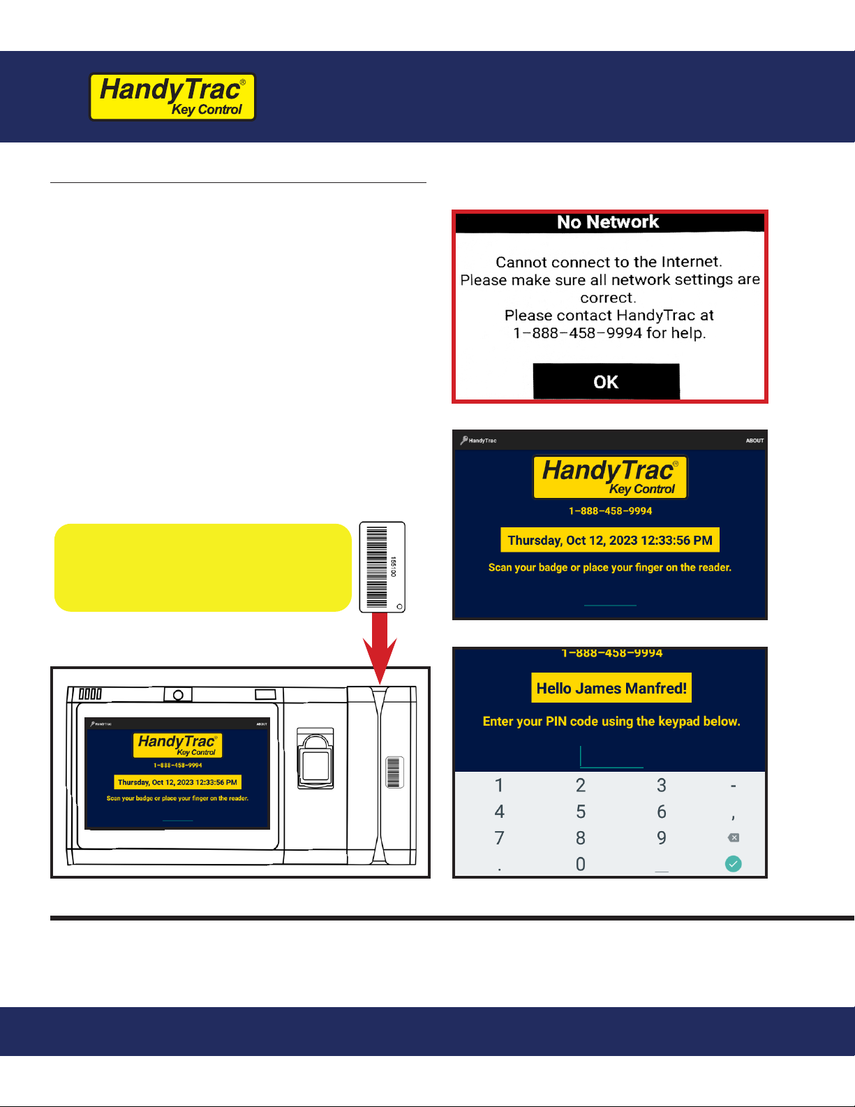
Option 2: Wireless Network
1. If you have the “No Network” popup
on the display, tap on “OK” to dismiss
it to display the Time and Date screen.
2. Once the system is at the main Time
and Date screen, sign in by scanning
the Master Badge through the barcode
reader on the right side of the system,
then type in the PIN using the on-
screen keyboard.
3. Make sure that the bar code is facing
to the left when scanning the Master
Badge through the barcode reader.
The Master Badge PIN is listed
on the inside ap of the small
envelope containing the Master
Badge.
If you cannot locate the Master Badge, or if you have any issues logging in with the
Master Badge, please call Technical Support for assistance at 1-888-458-9994.
Indice
Altri manuali HandyTrac Sistema di controllo


