HBM T10FS Manuale utente

Mounting Instructions
English
T10FS

Hottinger Baldwin Messtechnik GmbH
Im Tiefen See 45
D-64239 Darmstadt
Tel. +49 6151 803-0
Fax +49 6151 803-9100
www.hbm.com
Mat.: 7-2002.1315
DVS: A0785-150 HBM: public
04.2015
Hottinger Baldwin Messtechnik GmbH.
Subject to modifications.
All product descriptions are for general information only.
They are not to be understood as a guarantee of quality or
durability.

T10FS A0785-150 HBM: public 3
English
1 Safety instructions 6........................................
1.1 Markings used in this document 11..............................
1.2 Symbols on the product 12.....................................
2 Torque flange versions 13....................................
3 Application 15...............................................
4 Structure and mode of operation 16...........................
5 Mechanical installation 18....................................
5.1 Conditions on site 19..........................................
5.2 Installation orientation 20......................................
5.3 Installation options 20.........................................
5.3.1 Installation without dismantling the antenna ring
(without speed measuring system) 21...........................
5.3.2 Installation with subsequent stator mounting
(without speed measuring system) 22...........................
5.3.3 Installation example with couplings 23...........................
5.3.4 Installation example with joint shaft 23...........................
5.4 Mounting the rotor 24..........................................
5.5 Installing the stator 27.........................................
5.6 Installing the clamp fixture 30...................................
5.7 Mounting the slotted disc (optical speed measuring system) 32.....
5.8 Fitting the mounting elements (speed measuring system) 34........
5.8.1 Fixing the mounting elements 35................................
5.8.2 Mounting the torque flange with a speed measuring system 36......
5.9 Aligning the stator (speed measuring system) 38..................
5.9.1 Magnetic speed measuring system 38...........................
5.9.2 Optical speed measuring system 42.............................

4A0785-150 HBM: public T10FS
6 Electrical connection 44......................................
6.1 General information 44........................................
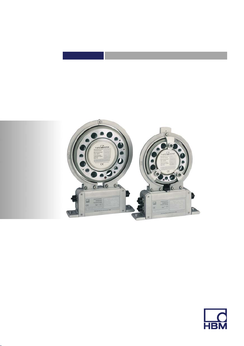
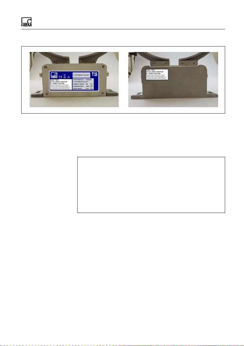
6.1.1 FCC and IC compliant installation
for US and Canada installation only 45...........................
6.2 Shielding design 47...........................................
6.3 Option 2, code KF1 48........................................
6.3.1 Adaptation to the cable length 48...............................
6.4 Option 2, code SF1/SU2 50....................................
6.5 Supply voltage 54.............................................
7 Calibration 56...............................................
7.1 Calibration Option 2, code KF1 56..............................
7.2 Calibration Option 2, code SF1/SU2 57..........................
8 Settings 58..................................................
8.1 Torque output signal, code KF1 60..............................
8.2 Torque output signal, code SF1/SU2 60.........................
8.3 Setting up the zero point 60....................................
8.4 Functional testing 62..........................................
8.4.1 Power transmission 62........................................
8.4.2 Testing the optical speed module 62.............................
8.5 Setting the pulse count 64.....................................
8.5.1 Magnetic speed measuring system 64...........................
8.5.2 Optical speed measuring system 68.............................
8.6 Vibration suppression (hysteresis) 70............................
8.7 Form of speed output signal 71.................................
8.8 Type of speed output signal 72.................................
8.9 Optical speed measuring system with a reference pulse 73.........
9 Loading capacity 75.........................................
9.1 Measuring dynamic torque 75..................................

T10FS A0785-150 HBM: public 5
10 Maintenance 77..............................................
10.1 Torque flange maintenance 77..................................
10.2 Speed module maintenance 77.................................
10.2.1 Magnetic speed measuring system 77...........................
10.2.2 Optical speed measuring system 77.............................
11 Dimensions 79..............................................
11.1 Rotor dimensions 79..........................................
11.2 Rotor dimensions with the magnetic speed system 81.............
11.3 Stator dimensions 83..........................................
11.4 Stator dimensions with the magnetic speed system 85.............
11.5 Mounting dimensions 87.......................................
12 Order numbers, accessories 89...............................
13 Specifications 91............................................
14 Supplementary technical information 107......................
14.1 Output signals 107.............................................
14.1.1 Output MD torque (connector 1) 107..............................
14.1.2 Output N: Speed and speed with a reference pulse (connector 2) 108.
14.1.3 Connector 2, double frequency, stat. direction of rotation signal 109..
14.2 Axial and radial run‐out tolerances 110............................

Safety instructions
6A0785-150 HBM: public T10FS
1 Safety instructions
FCC Compliance & Advisory Statement
Important
Any changes or modification not expressly approved by
the party responsible for compliance could void the user's
authority to operate the device. Where specified addi
tional components or accessories elsewhere defined to
be used with the installation of the product, they must be
used in order to ensure compliance with FCC regulations.
This device complies with Part 15 of the FCC Rules.
Operation is subject to the following two conditions: (1)
this device may not cause harmful interference, and (2)
this device must accept any interference received, includ
ing interference that may cause undesired operation.
The FCC identifier or the unique identifier, as appropri
ate, must be displayed on the device.
Model Measuring range FCC ID IC
T10S2 100 Nm, 200 Nm
2ADAT-T10S2TOS6 12438A-T10S2TOS6
T10S3 500 Nm, 1 kNm
T10S4 2 kNm, 3 kNm
T10S5 5 kNm
T10S6 10 kNm

Safety instructions
T10FS A0785-150 HBM: public 7
Fig. 1.1 Location of the label on the stator of the device
The preferred position of the FCC label is on the type
plate. If this is not possible for reasons of space, the
label can be found on the rear of the stator housing.
Model: T10S2
FCC ID: 2ADAT-T10S2TOS6
IC: 12438AT10S2TOS6
This device complies with part 15 of the FCC Rules. Operation is
subject to the following two conditions: (1) This device may not
cause harmful interference, and (2) this device must accept any
interference received, including interference that may cause unde
sired operation.
Label example with FCC ID and IC number
Industry Canada IC
This device complies with Industry Canada standard
RSS210.
This device complies with Industry Canada license-ex
empt RSS standard(s). Operation is subject to the follow
ing two conditions: (1) this device may not cause interfer
ence, and (2) this device must accept any interference,
including interference that may cause undesired opera
tion of the device.

Safety instructions
8A0785-150 HBM: public T10FS
Cet appareil est conforme aux normes d'exemption de
licence RSS d'Industry Canada. Son fonctionnement est
soumis aux deux conditions suivantes : (1) cet appareil
ne doit pas causer d'interférence et (2) cet appareil doit
accepter toute interférence, notamment les interférences
qui peuvent affecter son fonctionnement.
Important
Usage/Installation in the USA and Canada requires an
EMI suppressor. Please refer to chapter 6.1.1, page 45.
Designated use
The T10FS torque flange is used exclusively for torque
and rotation speed measurement tasks, and directly
associated control and regulatory tasks. Use for any
additional purpose shall be deemed to be not as
intended.
In the interests of safety, the transducer should only be
operated as described in the Operating Manual. It is also
essential to comply with the legal and safety
requirements for the application concerned during use.
The same applies to the use of accessories.
The transducer is not a safety element within the
meaning of its designated use. Proper and safe operation
of this transducer requires proper transportation, correct
storage, assembly and mounting, and careful operation.
General dangers of failing to follow the safety
instructions
The transducer corresponds to the state of the art and is
failsafe. The transducer can give rise to remaining
dangers if it is inappropriately installed and operated by
untrained personnel.

Safety instructions
T10FS A0785-150 HBM: public 9
Everyone involved with mounting, starting up,
maintaining, or repairing the transducer must have read
and understood the Operating Manual and in particular
the technical safety instructions.
Residual dangers
The scope of supply and performance of the transducer
covers only a small area of torque measurement
technology. In addition, equipment planners, installers
and operators should plan, implement and respond to the
safety engineering considerations of torque
measurement technology in such a way as to minimize
remaining dangers. On‐site regulations must be complied
with at all times. Reference must be made to remaining
dangers connected with torque measurement technology.
Conversions and modifications
The transducer must not be modified from the design or
safety engineering point of view except with our express
agreement. Any modification shall exclude all liability on
our part for any damage resulting therefrom.
Qualified personnel
The transducer must only be installed and used by
qualified personnel, strictly in accordance with the
specifications and with safety requirements and
regulations. It is also essential to comply with the legal
and safety requirements for the application concerned
during use. The same applies to the use of accessories.
Qualified personnel means persons entrusted with siting,
mounting, starting up and operating the product who
possess the appropriate qualifications for their function.

Safety instructions
10 A0785-150 HBM: public T10FS
Accident prevention
According to the prevailing accident prevention
regulations, once the torque flange has been mounted, a
covering agent or cladding has to be fitted as follows:
The cover or cladding must not be free to rotate.
The cover or cladding should avoid squeezing or
shearing and provide protection against parts that
might come loose.
Covers and cladding must be positioned at a suitable
distance or be arranged so that there is no access to
any moving parts within.
Covers and cladding must also be attached if the
moving parts of the torque flange are installed outside
peoples' movement and operating range.
The only permitted exceptions to the above requirements
are if the various parts and assemblies of the machine
are already fully protected by the design of the machine
or by existing safety precautions.
Warranty
In the case of complaints, a warranty can only be given if
the torque flange is returned in the original packaging.
Altri manuali per T10FS
2
Questo manuale è adatto per i seguenti modelli
5
Indice
Altri manuali HBM Strumento di misura


