IFM SD26 Series Manuale utente

Operating instructions
Flow meter compressed air / gases
SD25xx
SD26xx
SD55xx
SD56xx
SD65xx
SD66xx
SD85xx
SD86xx
SD95xx
80280071 / 00 01 / 2019
UK

2
Contents
1 Preliminary note���������������������������������������������������������������������������������������������������5
1�1 Symbols used ������������������������������������������������������������������������������������������������5
1�2 Warnings used�����������������������������������������������������������������������������������������������5
2 Safety instructions �����������������������������������������������������������������������������������������������6
3 Functions and features ����������������������������������������������������������������������������������������7
3�1 Pressure Equipment Directive (PED) ������������������������������������������������������������7
3�2 Applications ���������������������������������������������������������������������������������������������������7
4 Function���������������������������������������������������������������������������������������������������������������8
4�1 Processing of the measured signals��������������������������������������������������������������8
4�2 Switching output ��������������������������������������������������������������������������������������������9
4�3 Analogue output�������������������������������������������������������������������������������������������10
4�4 Consumed quantity monitoring [ImP] ����������������������������������������������������������12
4�4�1 Meter reading �������������������������������������������������������������������������������������12
4�4�2 Counter reset ������������������������������������������������������������������������������������12
4�4�3 Consumed quantity monitoring via pulse signals �������������������������������13
4�4�4 Consumed quantity monitoring via preset counter �����������������������������13
4�5 Measured value damping ����������������������������������������������������������������������������14
4�6 Low flow cut-off �������������������������������������������������������������������������������������������14
4�7 Simulation����������������������������������������������������������������������������������������������������14
4�8 Colour of the characters in the display ��������������������������������������������������������15
4�9 IO-Link ���������������������������������������������������������������������������������������������������������16
4�9�1 Additional functions via IO-Link ����������������������������������������������������������16
5 Installation����������������������������������������������������������������������������������������������������������16
5�1 Installation location ��������������������������������������������������������������������������������������17
5�2 Installation position ��������������������������������������������������������������������������������������17
5�2�1 Inlet and outlet pipe lengths����������������������������������������������������������������17
5�2�2 Orientation �����������������������������������������������������������������������������������������18
5�3 Installation in pipes ��������������������������������������������������������������������������������������18
6 Electrical connection������������������������������������������������������������������������������������������19
7 Operating and display elements ������������������������������������������������������������������������21
8 Menu������������������������������������������������������������������������������������������������������������������22
8�1 Process value display (RUN)�����������������������������������������������������������������������22
8�2 Main menu���������������������������������������������������������������������������������������������������23

3
UK
8�3 Extended functions (EF) ������������������������������������������������������������������������������24
8�4 Submenu OUT1�������������������������������������������������������������������������������������������25
8�5 Submenu OUT2�������������������������������������������������������������������������������������������27
8�6 Submenu CFG���������������������������������������������������������������������������������������������29
8�7 Submenus MEM, DIS ����������������������������������������������������������������������������������31
8�8 Submenus COLR, SIM ��������������������������������������������������������������������������������33
9 Set-up ����������������������������������������������������������������������������������������������������������������35
10 Parameter setting ��������������������������������������������������������������������������������������������35
10�1 Parameter setting in general ���������������������������������������������������������������������36
10�1�1 Select submenu��������������������������������������������������������������������������������36
10�1�2 Change to the process value display (RUN mode) ��������������������������36
10�1�3 Lock / unlock�������������������������������������������������������������������������������������36
10�1�4 Timeout���������������������������������������������������������������������������������������������37
10�2 Settings for volumetric flow monitoring������������������������������������������������������37
10�2�1 Limit monitoring OUT1 or OUT2 / hysteresis function ����������������������37
10�2�2 Limit monitoring OUT1 or OUT2 / window function ��������������������������37
10�2�3 Analogue signal volumetric flow OUT2���������������������������������������������37
10�3 Settings for consumed quantity monitoring �����������������������������������������������38
10�3�1 Quantity monitoring by pulse signal OUT1 or OUT2 ������������������������38
10�3�2 Quantity monitoring by preset counter OUT1 or OUT2 ��������������������38
10�3�3 Manual counter reset������������������������������������������������������������������������38
10�3�4 Time-controlled counter reset �����������������������������������������������������������38
10�3�5 Deactivation of the counter reset������������������������������������������������������38
10�3�6 Counter reset using an external signal ���������������������������������������������39
10�4 Settings for temperature monitoring ����������������������������������������������������������39
10�4�1 Limit monitoring OUT1 or OUT2 / hysteresis function ����������������������39
10�4�2 Limit monitoring OUT1 or OUT2 / window function ��������������������������39
10�4�3 Analogue signal temperature OUT2 �������������������������������������������������39
10�5 Settings for pressure monitoring����������������������������������������������������������������40
10�5�1 Limit monitoring OUT1 or OUT2 / hysteresis function ����������������������40
10�5�2 Limit monitoring OUT1 or OUT2 / window function ��������������������������40
10�5�3 Analogue signal pressure OUT2�������������������������������������������������������40
10�6 User settings (optional)������������������������������������������������������������������������������41
10�6�1 Standard display�������������������������������������������������������������������������������41
10�6�2 Standard unit of measurement for volumetric flow ���������������������������41
10�6�3 Standard unit of measurement for temperature��������������������������������41

4
10�6�4 Standard unit of measurement for pressure �������������������������������������41
10�6�5 Measured value damping �����������������������������������������������������������������42
10�6�6 Output logic ��������������������������������������������������������������������������������������42
10�6�7 Medium for SDx6xx units������������������������������������������������������������������42
10�6�8 Low flow cut-off���������������������������������������������������������������������������������42
10�6�9 Standard conditions��������������������������������������������������������������������������42
10�6�10 Zero-point calibration pressure�������������������������������������������������������42
10�6�11 Colour of the characters in the display �������������������������������������������43
10�6�12 Switch-on /switch-off delay �������������������������������������������������������������43
10�6�13 Error behaviour of the outputs ��������������������������������������������������������44
10�6�14 Restore factory setting��������������������������������������������������������������������44
10�7 Diagnostic functions ����������������������������������������������������������������������������������45
10�7�1 Read min/max values �����������������������������������������������������������������������45
10�7�2 Simulation�����������������������������������������������������������������������������������������45
11 Operation ���������������������������������������������������������������������������������������������������������46
12 Error correction������������������������������������������������������������������������������������������������46
13 Maintenance, repair and disposal��������������������������������������������������������������������48
14 Factory setting �������������������������������������������������������������������������������������������������49

5
UK
1 Preliminary note
Detailed instructions, technical data, approvals and other information via
the QR code on the unit / on the packaging or at www�ifm�com�
1.1 Symbols used
Instructions
> Reaction, result
[…] Designation of keys, buttons or indications
Cross-reference
Important note
Non-compliance may result in malfunction or interference�
Information
Supplementary note�
1.2 Warnings used
CAUTION!
Warning of personal injury�
Slight reversible injuries may result�

6
2 Safety instructions
• The device described is a subcomponent for integration into a system�
- The manufacturer is responsible for the safety of the system�
- The system manufacturer undertakes to perform a risk assessment and to
create a documentation in accordance with legal and normative requirements
to be provided to the operator and user of the system� This documentation
must contain all necessary information and safety instructions for the operator,
the user and, if applicable, for any service personnel authorised by the manu-
facturer of the system�
• Read this document before setting up the product and keep it during the entire
service life�
• The product must be suitable for the corresponding applications and environ-
mental conditions without any restrictions�
•
•
• If the operating instructions or the technical data are not adhered to, personal
injury and/or damage to property may occur�
• The manufacturer assumes no liability or warranty for any consequences
caused by tampering with the product or incorrect use by the operator�
• Installation, electrical connection, set-up, operation and maintenance of the unit
must be carried out by qualified personnel authorised by the machine operator�
• Protect units and cables against damage�

7
UK
3 Functions and features
The unit monitors the standard volume flow of compressed air in industrial use
and / or technical gases �
It detects the 5 process variables flow velocity, volumetric flow quantity, consumed
quantity, medium temperature and pressure�
All indications apply to standard volume flow to DIN ISO 2533, i�e� volume flow
at 1013 mbar, 15 °C and 0 % relative air humidity� The unit can be set to different
standard conditions �
This is a class A product� This product may cause radio interference in
domestic areas�
If required, take appropriate EMC screening measures�
3.1 Pressure Equipment Directive (PED)
The units comply with the Pressure Equipment Directive� They are designed for
stable gases of group 2 fluids and manufactured in accordance with sound engi-
neering practice�
3.2 Applications
SDx5xx
• Compressed air
SDx6xx
• Compressed air
• Argon (Ar)
• Carbon dioxide (CO2)
• Nitrogen (N2)
Selection of the medium to be monitored �

8
4 Function
• The volumetric flow is monitored by a calorimetric measuring system, the
measured signals are evaluated by the electronics�
• The unit detects the pressure and the media temperature of the volumetric flow
as additional process values�
• The unit features an IO-Link interface
• The unit displays the current process values�
• The unit has many self-diagnostic options�
• A simulation mode allows simplified set-up of the sensor�
4.1 Processing of the measured signals
The unit generates 2 output signals according to the parameter setting:
OUT1: 7 selection options
- switching signal for volumetric flow quantity limit
- switching signal for temperature limit
- switching signal for pressure limit
- switching signal for preset counter
- pulse signal for quantity meter
- IO-Link
- OFF (output switched to high impedance)
OUT2: 10 selection options
- switching signal for volumetric flow quantity limit
- switching signal for temperature limit
- switching signal for pressure limit
- switching signal for preset counter
- switching signal for quantity meter
- analogue signal for volumetric flow quantity
- analogue signal for temperature
- analogue signal for pressure
- input for external counter reset signal (InD)
- OFF (output switched to high impedance)

9
UK
4.2 Switching output
OUTx changes its switching status if it is above or below the set switching limits
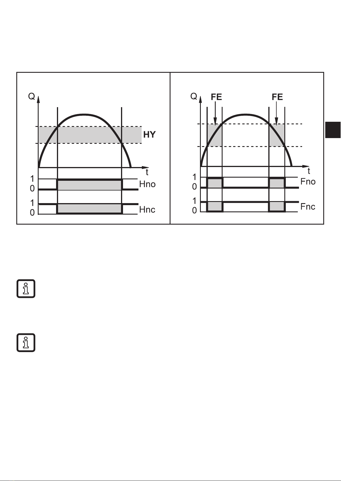
(flow, temperature or pressure)� Hysteresis or window function can be selected�
Example of volumetric flow monitoring:
Hysteresis function Window function
SP
rP FL
FH
SP = set point
rP = reset point
HY = hysteresis
Hno / Fno = NO (normally open)
FH = upper limit
FL = lower limit
FE = window
Hnc / Fnc = NC (normally closed)
When the hysteresis function is set, the set point (SP) is defined first and
then the reset point (rP) which must have a lower value� If only the set point
is changed, the reset point is changed automatically; the difference remains
constant�
When set to the window function, the upper limit value (FH) and the lower
limit value (FL) have a fixed hysteresis of 0�25 % of the final value of the
measuring range� This keeps the switching status of the output stable if the
volumetric flow varies slightly�

10
4.3 Analogue output
The unit provides an analogue signal that is proportional to the volumetric flow
quantity, the medium temperature or the pressure�
Within the measuring range the analogue signal is 4���20 mA�
The measuring range is scalable:
• [ASP2] determines at which measured value the output signal is 4 mA�
• [AEP2] determines at which measured value the output signal is 20 mA�
Minimum distance between [ASP2] and [AEP2] = 20 % of the final value of
the measuring range�
If the measured value is outside the measuring range or in the event of an internal
error, the current signal indicated in Fig� 1 is provided�
For measured values outside the display range or in case of a fault, messages are
displayed (cr�UL, UL, OL, cr�OL, Err; )�
The analogue signal in case of a fault is adjustable :
• [FOU] = On determines that the analogue signal goes to the upper final value
(21�5 mA) in case of an error�
• [FOU] = OFF determines that the analogue signal goes to the lower final value
(3�5 mA) in case of an error�
• [FOU] = OU defines that in case of a fault the analogue signal reacts as defined
by the current parameters�
Questo manuale è adatto per i seguenti modelli
8
Indice
Altri manuali IFM Strumento di misura

IFM
IFM efector300 SI0102 Manuale utente

IFM
IFM AS-i CompactModule M8 Manuale utente

IFM
IFM efector 300 SI0509 Manuale utente

IFM
IFM SV0527 Manuale utente

IFM
IFM efector300 VS3000 Manuale utente

IFM
IFM efector300 SA3000 Manuale utente

IFM
IFM SM4x00 Manuale utente

IFM
IFM efector300 SI6000 Manuale utente

IFM
IFM SI 5001 Manuale utente

IFM
IFM ZZ0600 Manuale