9-5 9-6
9.2.5. MAIN SUPPLY ASSEMBLY
This switched power supply converts power line voltages 90V-250V AC to 5V/+12V/-12V
DC. The 2AF/250V line fuse is installed on this assembly located near the line power
input. (To exchange the fuse you best unscrew the right hand side panel).
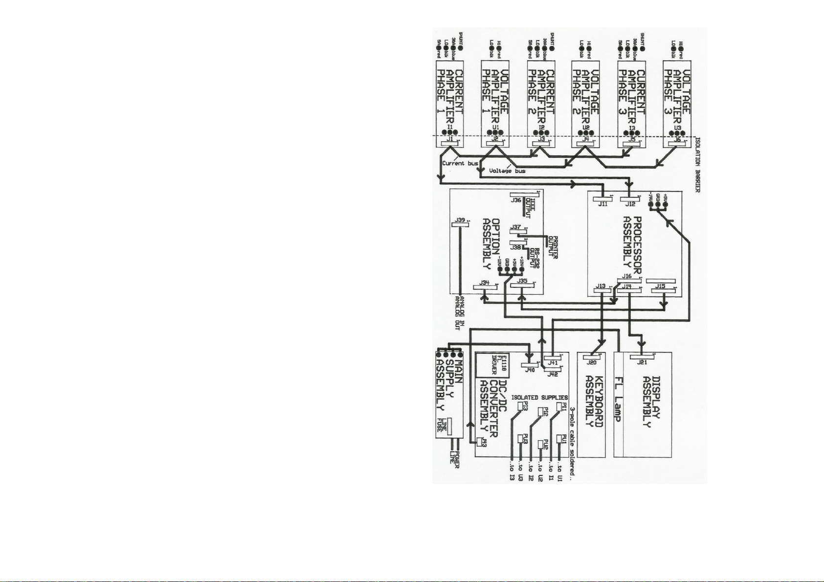
9.2.6. DC/DC CONVERTER ASSEMBLY
This assembly generates isolated DC supply voltages, 2 for the single phase- and 6 for
the three phase version (+10.5V/-15.5V) to deliver supply to the amplifier input section.
It also contains FL driver for the FL Lamp on the display.
Furthermore, this assembly distributes the supply to the processor (J41) and option
assembly (J42).
New Amplifier: DC/DC-Converter Assembly is missing. The individual DC/DC-
Converters are located on the amplifier boards.
The brightness adjustment for the LCD is located on the processor assembly, left corner
on top edge.
9.2.7. DISPLAY ASSEMBLY
The display assembly contains the control logic and memory to write ASCII- and
graphic data to the display. The FL lamp is mounted at the bottom of the display and
can easily be removed.
9.2.8. KEY BOARD ASSEMBLY
This assembly contains 11 switches for the front panel control of the Power Analyzer.
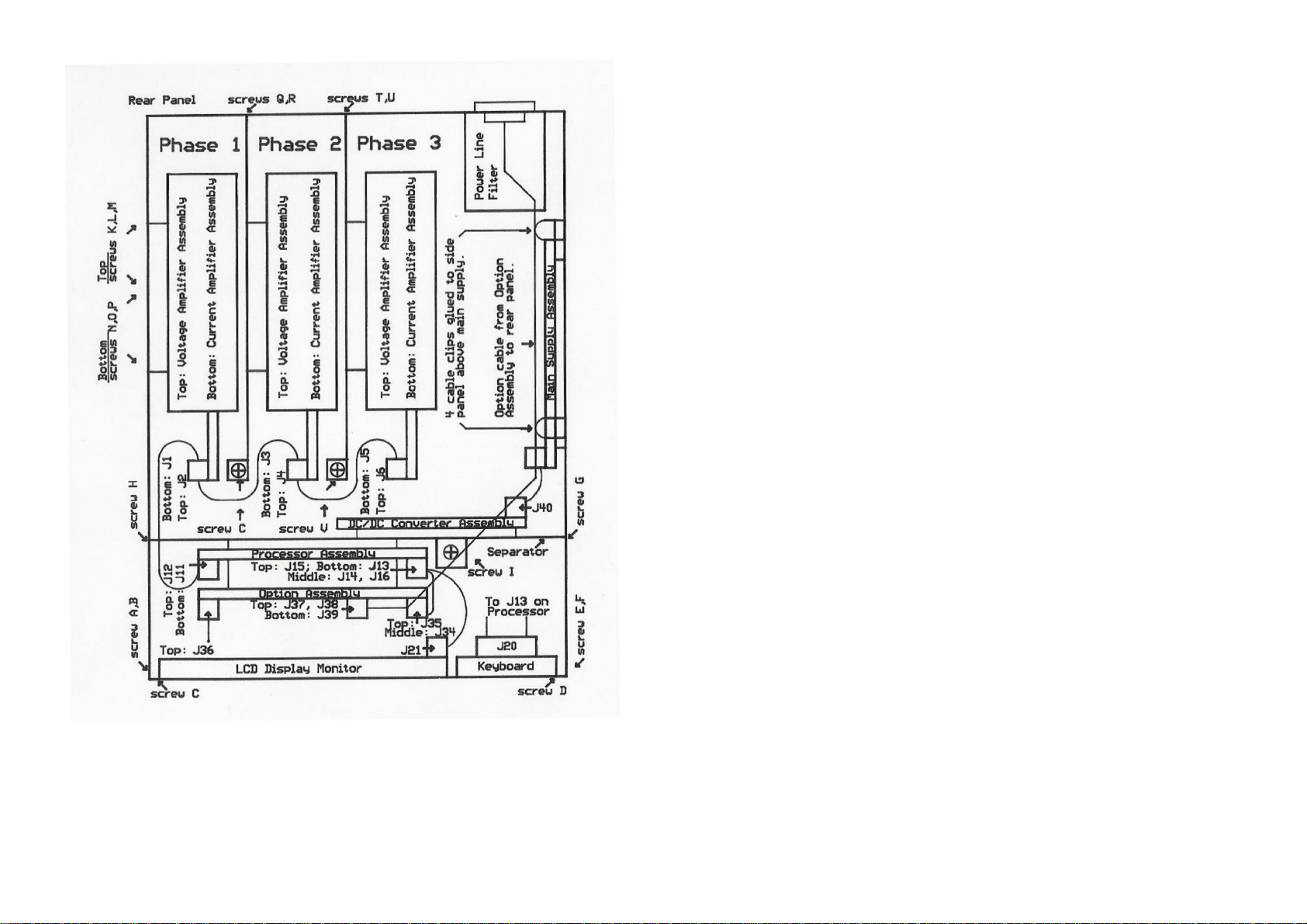
9.3. ASSEMBLY REMOVAL PROCEDURES
In this section we refer to Figure 9.2. for screw location.
9.3.1. REMOVING THE HOOD
Remove 3 screws on the left- and 3 screws on the right hand side of the case and pull
the hood over the top of the instrument. This gives you access to all assemblies of the
Power Analyzer.
9.3.2. REMOVING THE FRONT PANEL
The front panel contains the display - and keyboard assembly. To detach it remove 2
screws A, B along the left hand front edge, 2 screws E, F along the right hand front
edge, and 2 screws C, D along the bottom front edge. Disconnect the two flat ribbon
cable connectors (J21 and J20). Now you can put the front panel face down between the
side panels. The white cable from the FL lamp to the FL driver is still connected. In this
position you could install the option assembly. If you need to completely detach the front
panel detach the FL driver cable on the DC/DC converter board (J43). In a 3 phase unit
you may not be able to get to this connector. To disconnect tilt the separator by first
removing screw H on the left side panel, screw G on the right side panel, and screw I at
the bottom inside the case. Now move the separator towards the back panel to slide the
bolt (at location of screw I) out of its hole.
New Amplifier: It is possible to remove amplifiers without removing the separator first.
Start by unscrewing the left hand side panel to get access to amplifiers phase 1, etc.
9.3.3. REMOVING THE SEPARATOR
The separator is the central piece of the Power Analyzer and must be removed
whenever you want to remove amplifiers of phase 2 or phase 3, the Processor
Assembly, or the DC/DC Converter Assembly. Proceed as follows: Remove screw H on
the left side panel, remove screw G on the right side panel, and loosen screw I at the
bottom inside the case. The bolt that is fastened by screw I can be moved out of its hole
by moving the separator towards the back panel. Now disconnect those cables that
prevent removal.
New Amplifier: It is possible to remove amplifiers without removing the separator first.
Start by unscrewing the left hand side panel to get access to amplifiers phase 1, etc.
9.3.4. AMPLIFIERS PHASE 1 REMOVAL
CAUTION: Before removing an amplifier put a tag on it such as I Ph1, or U
Ph1 and make sure to reinstall it at its original location.
Amplifiers are coded for phase 1, 2, 3.
In a 3-phase unit you must first remove the separator.
To detach the voltage amplifier (on top) remove screws K, L, M on the left hand side
panel. Disconnect the plugs at the rear panel binding posts. Disconnect the flat ribbon
cable on the amplifier, disconnect the supply cable at connector PU1 and unscrew the
grounding cable at the DC/DC Converter Assembly.
Similarly you proceed to remove the current amplifier at the bottom: you remove screws
N, O, P first, then you disconnect the input binding posts. The shunt input cable is best
removed from the rear panel connector using pliers.