
Infratek 108B Manuale utente

USERS MANUAL 108B
SINGLE- TO FOUR PHASE
INFRATEK POWER ANALYZER

page 2
TABLE OF CONTENTS
1. Power Analyzer Features, Quick Overview, Safety 5
1.1 Standard Measure Mode ................................................................................................... 6
1.2 Logging Measure Mode ..................................................................................................... 7
1.3 Transient Measure Mode ................................................................................................... 7
1.4 Power-Speed Measure Mode (Option) ............................................................................... 8
1.5 Power Analyzer Rear Panel ............................................................................................... 9
1.6 Summary of 108B Power Analyzer Features ................................................................... 10
1.7 Safety Instructions ........................................................................................................... 11
2. Connection to Circuits 12
2.1 Measurement in 3-Phase mains Circuit ........................................................................... 12
2.1.1 Three Wattmeter Connection ............................................................................. 12
2.1.2 Aron Connection ................................................................................................. 13
3. 108B Mathematical Definitions and Specifications 14
3.1 Mathematical Definitions .................................................................................................. 14
3.2 Specifications .................................................................................................................. 18
4. Operating The Power Analyzer from the Front Panel 22
4.1 Operations in Standard Measure Mode ........................................................................... 23
4.1.1 Selecting Measure Mode .................................................................................... 23
4.1.2 Selecting Current Inputs using same Inputs for all Phases ................................ 24
4.1.3 Selecting individual current inputs per phase ..................................................... 24
4.1.4 Selecting Current Range using same range for all phases ................................. 25
4.1.5 Selecting Voltage Range using same range for all phases ................................ 25
4.1.6 Selecting Measurement Synchronization (Synchronization for all phases) ........ 26
4.1.7 Selecting Averaging Time ................................................................................... 26
4.1.8 Selecting Display Pages ..................................................................................... 26
4.1.9 Selecting Wave Forms (Graph) .......................................................................... 27
4.1.11 Selecting FFT Table and FFT Bar Graph ........................................................... 27
4.1.12 Selecting AC or DC+AC-Coupling ...................................................................... 27
4.1.13 Selecting Display RUN and Display HOLD ......................................................... 28
4.1.14 Resetting Energy ................................................................................................ 28
4.1.15 Selecting Display Quantities ............................................................................... 28
4.1.17 Selecting SETUP ................................................................................................ 31
4.2 Operations in Logging Measure Mode ............................................................................. 34
4.2.1 Valid Synchronization ......................................................................................... 34
4.2.2 Selecting CYCLES ............................................................................................. 34
4.2.3 What has to be observed when using Logging? ................................................. 35

page 3
4.3 Operations in Transient Measure Mode ........................................................................... 36
4.3.1 What is measured in Transient Measure Mode? ................................................ 36
4.3.2 Two Ways To Use Transient Measure Mode ..................................................... 36
4.4 Basics Of Power-Speed Measure Mode (Option) ............................................................ 38
4.4.1 What Is Measured In Power-Speed Measure Mode ........................................... 38
4.4.2 Operations in Power-Speed Measure Mode ....................................................... 38
5. Operating The Power Analyzer Using A Computer Interface 41
5.1 What Has To Be Observed When Using An Interface ...................................................... 41
5.2 What Has To Be Observed When Using The Interface Command Set ............................. 41
5.3 Computer Interface Command Set .................................................................................. 44
5.4 Composite Commands .................................................................................................... 44
5.5 Reading voltages, reading and writing voltage scale factors ............................................ 45
5.6 Reading currents, reading and writing current scale factor ............................................... 46
5.7 Reading power, apparent power, and reactive power ...................................................... 47
5.8 Reading energy, charge, and time ................................................................................... 47
5.9 Reading frequency, impedance, and phase angle. .......................................................... 48
5.10 Reading/writing range of harmonics, number phases for output, and cycle for Logging ... 48
5.11 Read and write display, RS232 Baud Rate, IEEE-488 address........................................ 49
5.12 Read and write common control commands. ................................................................... 49
6. Computer Operating Software 51
6.1 Installing Computer Operating Software .......................................................................... 51
6.2 108A Data Window (Computer Software) ........................................................................ 52
6.2.1 Select Interface .................................................................................................. 52
6.2.2 Select instrument mode ...................................................................................... 53
6.2.3 Select software mode ......................................................................................... 54
6.2.4 Operate the computer software .......................................................................... 54
6.2.5 Input, Ranges, Synchronization, Aperture selection ........................................... 55
6.2.6 Phase Slider for selecting individual settings per phase ..................................... 55
6.2.7 Curve .................................................................................................................. 55
6.2.8 FFT Numerics (Harmonics) ................................................................................ 56
6.2.9 FFT Bar Graph (Harmonics) ............................................................................... 56
6.2.10 Vector Graph (Phase Angle) .............................................................................. 56
6.2.11 IEC Data Window ............................................................................................... 57
6.2.12 Control / Setting Window .................................................................................... 59
6.2.13 Logging-, Transient-, Power Speed Measure Mode ........................................... 61
7. Analog Input and -Output 62
7.1 Analog Input And Output Specification ............................................................................. 63

page 4
7.2 Programming The Analog Outputs ................................................................................... 63
7.3 Using Inputs for Motor Testing (See also 4.1 Motor Testing) ........................................... 64
7.4 Using Low Current Shunt for Standby Power Measurement ............................................ 65
8. Data Management 66
8.1 Operating the Power Analyzer using the USB Interface ................................................... 66
8.2 Operating the Power Analyzer using the Ethernet Interface ............................................. 66
8.3 Measurement Data from the Power Analyzer (USB) to Computer .................................... 67
9. Calibration via 108B Front Panel 68
9.1 Equipment Needed .......................................................................................................... 68
9.2. Calibration Procedure ...................................................................................................... 68
9.2.1 Voltage Calibration At 60Hz ............................................................................... 68
9.2.2 Current Calibration At 60Hz, Shunt Input Calibration ......................................... 69
9.2.3 Storing The Calibration Constants ...................................................................... 70
9.3. A Few Practical Hints ....................................................................................................... 70
9.4. 108B Calibration using Windows Operating Software (LabView) ..................................... 71
9.4.1 Equipment Needed ............................................................................................. 71
9.4.2 Calibration Procedure ......................................................................................... 71
9.4.3 Voltage Calibration At 60Hz ............................................................................... 71
9.4.4 Current Calibration At 60Hz (IN 5A) ................................................................... 72
9.4.5 Current Calibration At 60Hz (IN 1A) ................................................................... 73
9.4.6 Current Calibration At 60Hz (IN 30A) ................................................................. 74
9.4.7 Current Calibration At 60Hz (SHUNT) ................................................................ 74
9.4.8 Storing The Calibration Constants ...................................................................... 75
9.4.9 A Few Practical Hints ......................................................................................... 75
page 5
1. POWER ANALYZER FEATURES, QUICK OVERVIEW, SAFETY
The Infratek 108B High Precision Power Analyzer is available in 1-, 3- and 4- phase versions.
All voltage inputs (ranges 0.3V up to 1500Vpeak) and all current inputs (1.5mA up to 1A;
15mA up to 5A; 1A up to 40A; and current shunt inputs 60mV up to 6V) are potential free and
exhibit
Excellent low noise
Common mode suppression
DC-stability
Wide frequency range (2MHz)
Very low self-heating on current inputs.
There is no need to fiddle with dc-compensation, or changing current plug-ins. All is built into
the input sections of the Power Analyzer, ready to be used.
Your intuition will guide you to operate the Power Analyzer touch screen correctly. With basic
knowledge of power measurement, you will be able to change the settings to your needs. Al-
most all setting changes are accomplished with two touches on the display screen or two
clicks with the mouse.
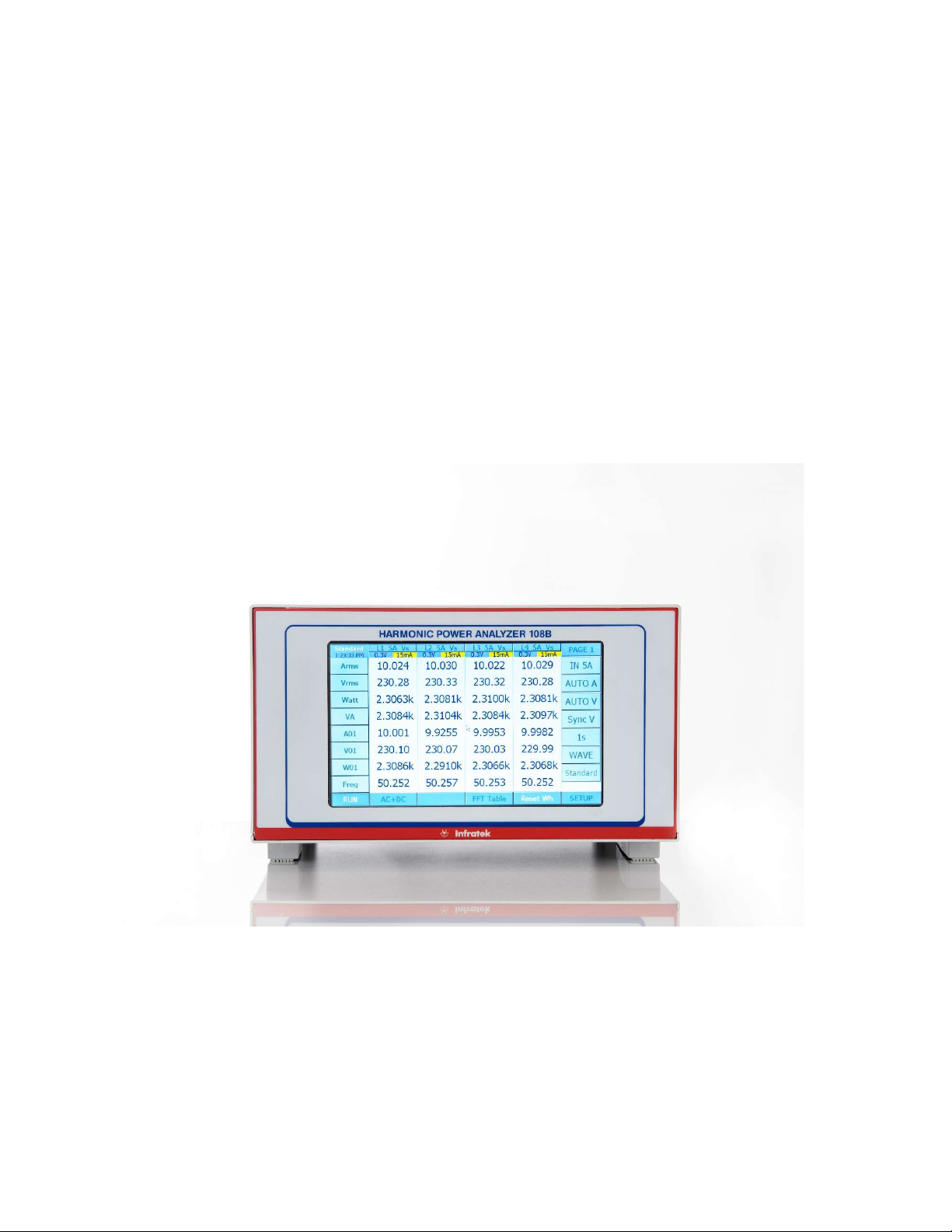
Figure 1.1 Shows the display of a 4-phase instrument in “Standard Mode”.
Figure 1.1 shows the display of a 4-phase instrument in “Standard Mode”. To change the cur-
rent range from 15mA to 500mA touch the button “AUTO A”. A pop-up window is presented
from which you select “500mA”. Now the Power Analyzer is in 500mA current range (manual
ranging).

page 6
Figure 1.2 108B Value Selection Table
Just as simple is to change the quantity at the bottom line “Freq” to Arectified mean (Arect).
Touch “Freq” at the left side of the display. This will present you a value selection table as
shown in Figure 1.2. Now touch “Arect” which brings you back to Figure 1.1 with the bottom
line quantity changed to “Arect”.
Four different measure modes enhance the 108B Power Analyzer capabilities. These are:
standard measure mode, logging measure mode, transient measure mode, and power-speed
measure mode.
1.1 S
TANDARD
M
EASURE
M
ODE
In the Standard Measure Mode 280 quantities per phase are continuously measured
(no gaps) and are updated. Values can be displayed on four display pages, can be saved in
internal memory, or on a memory stick, or can be transferred via Interface to a computer.
Touching “WAVE” will display a sub-menu which lets you select the current-, voltage-, and
power wave forms of any phase.
Select “OFF” (Wave OFF). Now you have access to the buttons “FFT Table”. Touching
“FFT Table” selects “FFT L1”. On five pages you can now view the harmonics of current, volt-
age, power, and phase angle (harmonics 1 to 40 for current and voltage, harmonic 1-21 for
power and phase angle).
Similarly, selecting “FFT Bar” the bar graph of the harmonics will be displayed in percent of
the fundamental (1. harmonic).
Touching “FFT L1” will toggle to “FFT L2”, “FFT L3”, and so on.
page 7
1.2 L
OGGING
M
EASURE
M
ODE
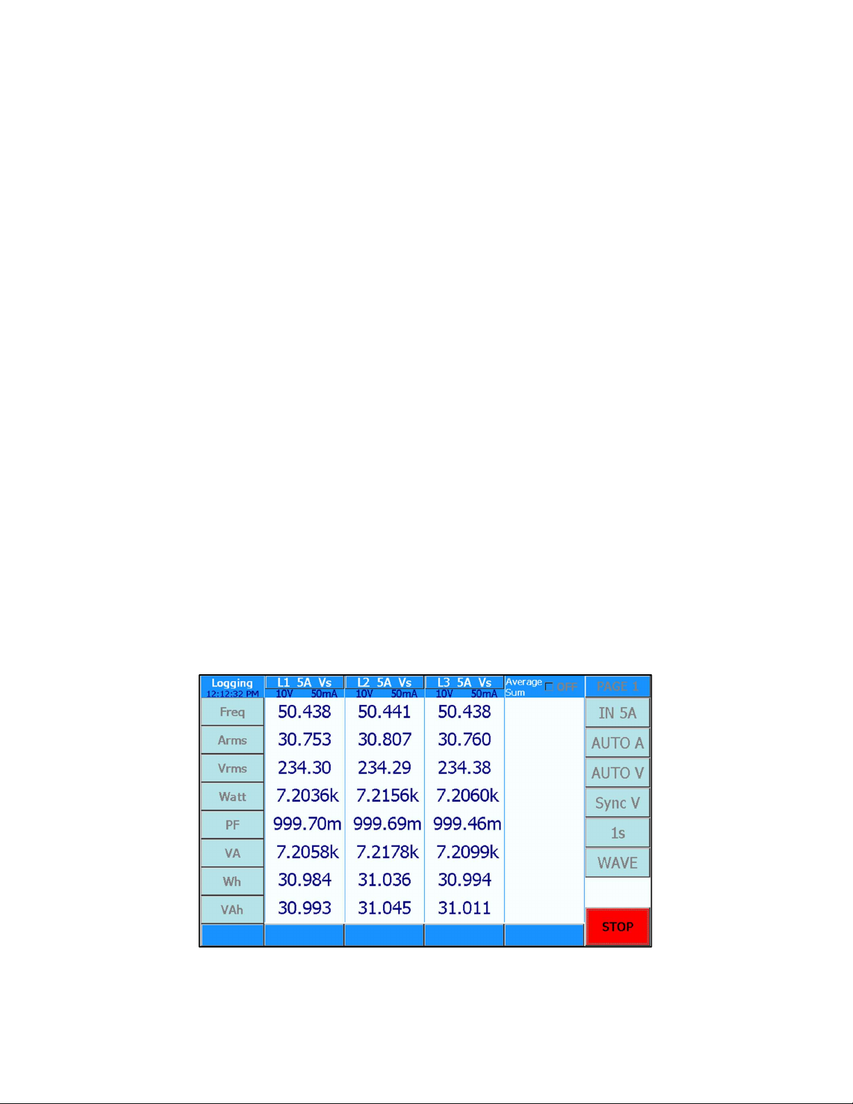
The basic operation is as follows: Select the number of cycles for which you desire a periodic
data output to the RS232- / USB-interface. If you perform measurements on the 50Hz power
line and you select cycles = 1 you obtain new data every 20ms; if you select cycles = 30000
you obtain new data every 10 minutes.
Before starting the measurement, a valid synchronization signal 5Hz to 2kHz must be applied
to all installed phases of your Power Analyzer. Select Sync A, Sync V, or S_Ext V. Touch the
START-button to start the measurement, touch the STOP-button to stop it. DC signals can
also be measured (e.g. DC-motors). For DC you must apply an external synchronization sig-
nal in the frequency range 5Hz – 2kHz (select EXT synchronization).
Furthermore, the frequency of the synchronization can be varied up and down as much as
10% per second.
From every phase you obtain 8 values: frequency, RMS current, RMS voltage, power, power
factor, apparent power, energy Wh, and apparent energy VAh.
If you select the baud rate of 463.2 kBaud (in SETUP) a 4-phase Power Analyzer transmits
8 x 4 = 32 values in less than 20ms. This can be used to analyze the start-up behaviour of
power systems.
1.3 T
RANSIENT
M
EASURE
M
ODE
The transient measure mode can be used in two ways: You can catch current-, voltage-, and
power wave forms in a start-up on all phases simultaneously or you can view all wave forms
at a critical operating point in Standard Measure Mode (up to maximum 4 phases).
The duration of the measurement is set by changing in the SETUP menu the Transient-id
from 0 to 7. Sections of the wave forms can be expanded by simply touching one of the 4
“Zoom Sectors” (maximum zoom factor is 256).
For proper operation you must apply signal synchronization to all installed phases of your
Power Analyzer.
Figure 1.3 108B 3-Phase Power Analyzer Display in Logging Measure Mode

page 8
1.4 P
OWER
-S
PEED
M
EASURE
M
ODE
(O
PTION
)
This measure mode analyzes the performance of electric devices such as electric cars.
In 20ms intervals the following data are stored in internal memory: RMS current, RMS volt-
age, power, apparent power, energy, apparent energy, and speed of an axis or a wheel. Rms
current and –voltage are average values of the number of phases used, power and energy
are the sums of phases used.
Power speed measurements can be performed on DC- as well as AC-drives using either
phase 1, or phase 1 and phase 2, or using phase 1, 2, and phase 3 of the Power Analyzer.
At the end of a measurement cycle (maximum 11 seconds) data versus time are plotted, can
be expanded to view details, or can be stored.
Figure 1.4 108B 3-Phase Power Analyzer in Power-Speed Measure Mode

page 9
1.5 POWER ANALYZER REAR PANEL
Figure 1.5 shows the 108B rear panel with four phases installed. Every phase consists of a
potential free voltage input along the top side.
Below the voltage inputs are the 40A input, and the 5A input (7A max.) with common Lo
socket. Above the 40A socket is the 3 pole Amphenol socket for the 1A input and shunt input.
It is normally covered with the shunt short circuit cap.
Figure 1.5 Rear panel of a 4 Phase 108B Power Analyzer
All four current inputs are referenced to the black Lo socket and are potential free.
Figure 1.6 3 pole Amphenol Socket for 1A current input and shunt input
For use of 1A input remove the shunt short circuit cap and insert the 1A adapter. The 1A
adapter is the Hi input, and the black current socket is the 1A Lo.
Caution: When 1A adapter is removed the shunt short circuit cap must be inserted.
1A Input Hi, Lo at black 4mm
socket
Short circuit when clamp not used.
Shunt Hi
Shunt
Lo

page 10
1.6 SUMMARY OF 108B POWER ANALYZER FEATURES
Available as 1-, 3- and 4-phase instrument.
Highest precision available: 0.02 % reading + 0.02 % range.
18bit measurement resolution. High accuracy at 10 % full scale.
Wide angle, touchscreen TFT color display (800 x 480 pixels).
Simple to operate, most settings in 2 steps (2 touches).
Settings per phase for V- A-ranges, current inputs, and synchronization.
Standard-, Logging-, Transient-, Power-Speed measurement functions.
Standard: calculates all quantities of power electronics, including motor- and
transformer values, harmonics, energies, analog inputs, and speed.
Fast data transfer; up to 3400 values per second.
High DC precision for solar applications.
Includes 4 current inputs: 1mA - 1A, 15mA - 5A, 1A - 40A, shunt.
Voltage Ranges: 0.3V to 1000V.
USB memory stick >4GByte
USB interface for downloading measurement data
Optional interfaces: RS232, USB, Ethernet, IEEE-488
Optional: 2 frequency inputs max 150kHz, 6 analog inputs, and 12 analog outputs.
Interface commands for fast data transmission.
Operating software under Windows, LabView Driver
Reasonably priced by virtue of smart design.
Simple servicing, modular concept, pre-calibrated input amplifiers.
Optional high precision, broadband, current sensors.
Upgrading the number of installed phases is possible at any time
Indice
Altri manuali Infratek Strumento di misura


