
LINDR PYGMY 20 Manuale utente

CZECH UP YOUR BEER
COOLING AND DISPENSING SYSTEMS
english INSTRUCTIONS FOR USE
FLOW TYPE CONTACT COOLER LINDR

COOLING AND DISPENSING SYSTEMS 18
Introduction:
Thank you for purchasing a Lindr product.
This instruction manual is for models:
PYGMY 20, PYGMY 20/K, PYGMY 25, PYGMY
25/K, PYGMY 30/K pro, KONTAKT 40, KON-
TAKT 40/K, KONTAKT 40/K pro,
and GREEN LINE models:
PYGMY 25, PYGMY 25/K, KONTAKT 40, KON-
TAKT 40/K, KONTAKT 70, KONTAKT 70/K,
KONTAKT 155, KONTAKT 155/K, KONTAKT
155/R
General instructions and precautions
Safety instructions:
Respect the basic safety instructions
given by the manufacturer. This cooling
equipment is designed for ow type cooling
of beverages dispensed from kegs. Any other
use is considered inaccessible, and therefore
dangerous. The supplier shall not be liable
for damages caused by improper use.
DO NOT USE THE EQUIPMENT FOR ANY OTHER PURPOSES THAN
WHAT IT IS INTENDED FOR BY MANUFACTURER!
General safety rules
Follow these safety instructions.
The supplier shall not be liable for damages
caused by activities performed on this devi-
ce without following the instructions below!
This appliance can be used by children aged
8 years and older people with reduced phys-
ical, sensory or mental
capabilities, or lack of experience and
knowledge, should under supervision, or
have been instructed about using the appli-
ance safely and understand any potential
hazards.
Children should not play with the appliance.
Cleaning and maintenance of the appliance
cannot be performed by unattended chil-
dren.
CAUTION: Before connecting the main
power supply check if the voltage and
frequency match the data shownon the
device.
CAUTION: Always make sure the power
socket to connect the cooler is eqipped with
sucient circuit breaker (16A depending on
the type) according to ČSN 33 1500.
CAUTION: Before any intervention on
the device, eg cleaning and machine
maintenance, ALWAYS disconnect the
appliance from the electrical supply: set the
thermostat to the „O“ position and pull out
the plug.
CAUTION: Never put tools or other objects
into the propeller fan.
CAUTION: Never touch the electrical parts
with wet or damp hands.
CAUTION: To ensure the performance of the
cooling unit, never block the air inlet.
WARNING:
When sanitizing, the water temperature
must not be higher than 25 ° C!
CAUTION: Always make sure the power
socket is in a freely accessible place in case
of the need to pull the plug immediately.
CAUTION: When pulling the plug out of
the socket, grasp the plug and pull out.
Do not pull the supply cord under any
circumstances or you may cause a damage.
CAUTION: To disconnect the device
completely, pull the plug out of the
electricity socket.

ˇ
FLOW TYPE CONTACT COOLER LINDR
19
CAUTION: In case of damage to the
electrical circuit, you have to call trained
service technician. In no case should you
repair it yourself.
CAUTION: Special maintenance such as
cleaning and maintaining the cooling
system, must be carried out by trained,
authorized technicians who are familiar
with cooling and electrical systems.
CAUTION: When sanitizing with chemicals
ALWAYS wear rubber gloves.
CAUTION: After unpacking, place the cooler
in a way so that the heat that is generated
by the cooling unit and it can be suciently
ventilated.
CAUTION: The cooler must be placed
indoors on a dry and horizontal place that
is stable.
CAUTION: There should be no objects
placed on the cooler that would block the
air circulation.
Installation and placing:
Place the cooler on the xed pad in a
horizontal position and before connecting
for the rst time, allow the machine to
settle for about 2 hours to acclimatize to the
surrounding conditions.
CAUTION:
THE CHILLER SHOULD NOT BE PLACED ON ITS SIDE IN ANY
CIRCUMSTANCE, AND NOT EVEN DURING TRANSPORTATION.
Use the machine best in cold and well
ventilated room. The machine is intended
for use at ambient temperature min. 6 ° C
and max. 28 ° C. Do NOT use or store the
machine at ambient temperature below 0 °
C. The machine is intended for use a normal
environment according to ČSN 33 2000-3
and is included in CLIMATE CLASS N.
This Machine MUST NOT BE CLOSE TO HEAT SOURCES, OR
EXPOSED to direct sunlight and rain.
For the proper operation, it is important not
to cover any of the ventilating holes.
Notice:
The electrical equipment must be revised
and checked in terms of ČSN 33 1600 edition
2 by a knowledgeable and authorized
person. Service-spare parts, required
revisions and inspections are carried out by
LINDR.

COOLING AND DISPENSING SYSTEMS 20
beverage
outlet
the packaging includes:
Beer dispensing tap (1.)(models with 2 taps contain 2 pieces
of beer dispensing taps) drip tray (2.) Service Key for the taps
(3.).
Connecting of the dispensing tap:
1.
Rotate the compensator lever (1.) in a downward direct (see
picture). You will set the most suitable or your desired ow
with the compensator lever on the dispensing tap.
2.
Fit the tap in an upright position onto the body with a cap
nut.
3.
Secure the cap nut and rotate to the left. (Loosen in the
opposite direction.)
4.
Tighten with the supplied key.
5.
Screw the plastic tting F 5/8 x 9.5 mm onto the coupler
(beeroutlet).

ˇ
FLOW TYPE CONTACT COOLER LINDR
21
silikone
valve
air inlet
beverage
inlet
ATTENTION!
Before you screw the silicone plastic tting onto the thread
5/8, make sure that there is a silicone non-return valve on the
keg coupler (air in let).
6.
Screw the plastic tting F 5/8x8.0 mm onto the coupler (air
in let)
Beverage connection:
7.
Connect the cooling system with a coupler by inserting 3/8
into the plastic tting, which is placed on the back part of
thecooler.
8.
Insert the beverage tube 3/8 going from the cooling machine
into the plastic tting F5/8 x 9,5 mm (outlet for the beverage
on the keg coupler)
9.
Connect the air supply onto the plastic tting F 5/8 x 8 mm or
connect with built-in compressor.
For models with inbuilt air compressor the process of connecting an airtube is the same as
with the beverage tube, the only dierence are the used plastic ttings and the tube 5/ 16.
The plastic tting on the back of the cooler is labelled with an AIR sign. (see connection
A.,C.)

COOLING AND DISPENSING SYSTEMS 22
7.
4.
5.
6.
1.
2.
3.
5.
7.
2.
3.
4.
6.
1.
Connection A: using a machine with inbuilt compressor and one dispensing tap
1. Beverage inlet
2. Air outlet
3. ON/OFF switch for
the compressor
4. Keg coupler (S-type,
A-type, M-type)
5. Plastic tting
F 5/8x9.5 mm
6. Plastic tting
F 5/8x8 mm
7. Beverge
Connection B: using a machine with one dispensing tap together with a mini CO2 bottle
1. Beverage inlet
2. Keg coupler (S-type,
A-type, M-type)
3. Plastic tting
F 5/8x9.5 mm
4. Plastic tting
F 5/8x8 mm
5. Pressure reducer for
Co2 bootle mini
6. Plastic tting
F 7/16x8 mm
7. Beverage

ˇ
FLOW TYPE CONTACT COOLER LINDR
23
Connection C: using an inbuilt compressor to pressurize (for machines with two dispensing taps)
1. Beverage inlet
2. Air outlet
3. Keg coupler (S-type,
A-type, M-type)
4. Plastic tting
F 5/8x9.5 mm
5. Plastic tting
F 5/8x8 mm
6. Plastic tting
Y 8x8x8 mm
7. Beverge
8. ON/OFF switch for
the compressor
Built-in air compressor
Only for models with built-in air compressor PYGMY 20/K, PYGMY 25/K, PYGMY 30/K pro,
KONTAKT 40/ K, KONTAKT 40/K pro and models GREEN LINE PYGMY 25/ K, KONTAKT
40/K, KONTAKT 70/ K, KONTAKT 155/ K.
The mini air compressor is built into the cooling system. Automatic pressure control is
set to 2.8-3.2 bar. For Kpro models there is the possibility of continuous pressure control
in the range of 1.0-3.4 bar. The set pressure value is displayed on the manometer in bars.
The compressor can be switched o by the switch itself. The air outlet from the cooler is
closed by a DM 5/16 (8mm) fast tting and marked AIR. The air compressor is maintenan-
ce-free, equipped with a molecular air intake lter.
2.
3.
6.
7.
3.
4.
4.
5.
5.
1.
8.

COOLING AND DISPENSING SYSTEMS 24
Connection D: using a machine with two dispensing taps together with a C02 bottle
1. Beverage inlet
2. Keg coupler (S-type,
A-type, M-type)
3. Plastic tting
F 5/8x9.5 mm
4. Plastic tting
F 5/8x8 mm
5. Plastic tting
F 5/8x8 mm
6. Pressure reducer
CO2
7. Plastic tting
F 7/16x8 mm
8. Beverage
Other options of pressurizing:
By compressor PUMA 1 HP a 1/2HP, compressor LEONARDO 1HP, compressor AIRCRAFT
1HP or with N2 bottle and C02.
Connection E: KONTAKT 155/R for use to pressurize the traditional CO2 bottle (or mixed gas of CO2 and N2 -
reduction)(for machines with two dispensing taps)
1. Beverage inlet
2. CO2 outlet
3. Pressure Control
4. Keg coupler (S-type,
A-type, M-type)
5. Plastic tting
F 5/8x9.5 mm
6. Plastic tting
F 5/8x8 mm
7. High pressure hose
with a sleeve nut
W21.8 for the
cylinder with thread
G3/4 is needed to
use the adapter for
K155/R
8. Beverge

ˇ
FLOW TYPE CONTACT COOLER LINDR
25
Connection and regulation of KONTAKT 155/R to CO2 bottle
1. Screw the plastic ttings onto the keg coupler (see picture 5. and 6./ page 4 a 5).
2. Insert the hose 3/8 and 5/16 into the plastic ttings on the keg coupler
(see picture 8. and 9./ page 5).
3. Connect the hose 3/8 and 5/16 with the plastic ttings placed on the cooling machine
according to the description on the label. The label is located above the ttings.
4. Attach the high pressure hose to the CO2 bottle using a cap nut (7.).
5. Put the coupler on the beverage keg and make sure the coupleris in the closed position
(upper position).
6. Open the shut-of valve on the CO2 bottle and set the desired pressure for both lines
using the srews on the top of the machine (No.3). (The pressure setting is displayed on
the manometer of the front side of the cooling machine).
7. Connect the keg using the keg coupler.
COOLING AND DISPENSING SYSTEMS 26
CHECK IF ALL THE CONNECTIONS ARE PROPERLY SEALED.
lf there is everything in order, check the
thermostat settings (o position). Connect
the cooler is plug to the electrical network.
Then use the dispense head, bump a keg
and pressure the keg up to 1.0-3.4 bars and
then by dispense tap pull a drink. lf there
some water or cleaning solution left, hold
the tap until it will ow a drink only. Set the
thermostat to the required temperature. lf
you use a cooler for soft drinks cooling, set
the thermostat hand-barrow to the level
S only - not more, otherwise the drinks
could freeze in the cooler loops and could
damage the whole systém inside the cooler.
FOR MODELS WITH IN BULIT AIR COMPRESSOR, THERE IS
PRESSU RE SET AUTOMATICALLY (from 2.8 to 3.2 bar).
Temperature and setting:
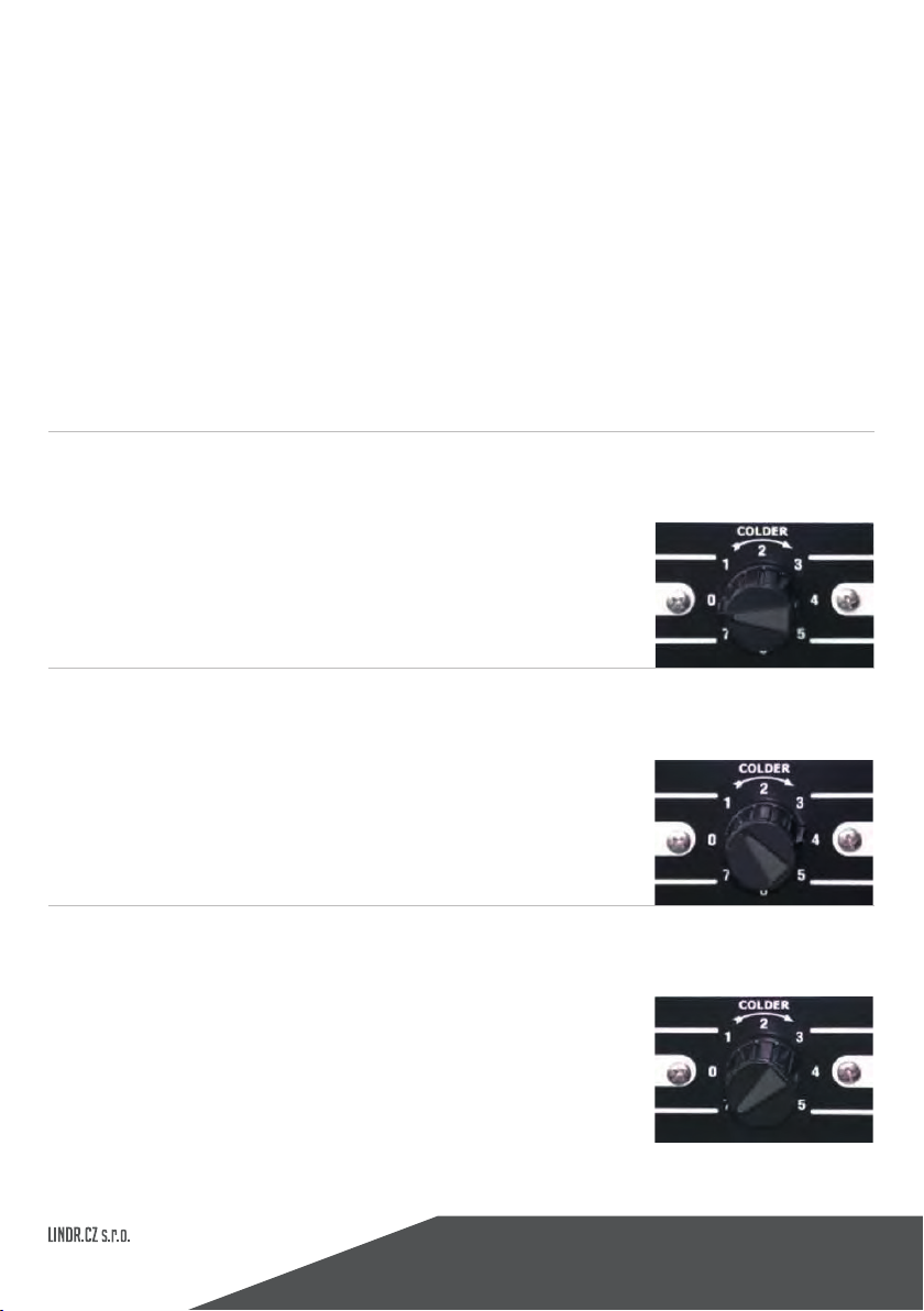
10.
The temperature of the cooled beverages is controlled
manually by a thermostat in the range between 2 °C to 8 °C.
The thermostat has a controller from 1 to 7.
0= switched o
. č.1 = max. temperature
beverage 8 °C
11.
Then connect to a power supply. lf you are using this cooler
for cooling non alcoholic beverages, then set the manual
thermostat on the front of the machine to a 5 maximum,
otherwise the machine might freeze or getdamaged.
č.7 = min. temperature
beverage 2 °C
Questo manuale è adatto per i seguenti modelli
7
Indice
Altri manuali LINDR Elettrodomestico da cucina


