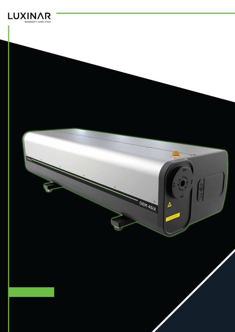
Luxinar OEM 65iX Manuale utente
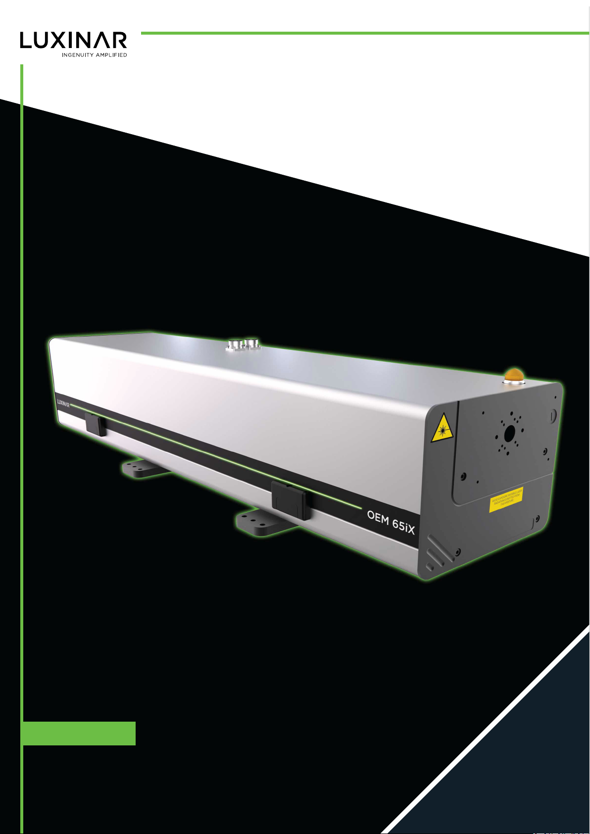
USER MANUAL OEM 65iX
Sealed CO2 laser source

© 2022 Luxinar Ltd. All rights reserved.
Revision history
1 18/01/2022 — CR 651478: Reorder and modularise content, change to XML format. Update DC PSU and safety sections.
2 28/09/2022 — CR 651729: Green diode pointer.
3 28/10/2022 — CR 651940: UKCA marking and safety section updates
4 05/07/2023 — CR 652584: Safety label updates
This manual is copyrighted with all rights reserved. Under copyright laws, this manual may not be copied in
whole or part or reproduced in any other media without the express permission of Luxinar Ltd. Permitted
copies must carry the same proprietary and copyright notices as were affixed to the original. Under law,
copying includes translation into another language.
Please note that while every effort has been made to ensure that the data given in this document is accurate,
the information, figures, illustrations, tables, specifications and schematics contained herein are subject to
change without notice. Contact Luxinar Aftersales to verify that you have the latest version of this manual.

Aftersales contact details
Luxinar Ltd
Meadow Road
Bridgehead Business Park
Kingston upon Hull
HU13 0DG
U.K.
Tel.: +44 (0) 1482 650088
www.luxinar.com
For Aftersales Service, contact: [email protected]
For Parts, contact: [email protected]
Luxinar GmbH (Germany)
Röntgenstrasse 6
21465 Reinbek
Germany
Tel.: +49 (0)40 883624-60
www.luxinar.com/de
Luxinar Ltd (Italy branch office)
Via Pavia 11/B
10098 Rivoli
Torino
Italy
Tel.: +39 (0)11 19118353
www.luxinar.com/it
Luxinar Ltd (Korea branch office)
#409, A-dong (Bundang Suji U-Tower)
767, Sinsu-ro, Suji-gu, Yongin-si, Gyeonggi-do
Republic of Korea 16827
Tel.: +82 (0)31 546 0861
www.luxinar.com/ko
Luxinar Laser Technology (Shanghai) Co., Ltd (China)
Room 02, 5th Floor, 8# Jiafeng Road
Shanghai Pilot Free Trade Zone
Shanghai, China
200131
Tel.: +86 21 6106 9917
www.luxinar.com/zh-CN
Luxinar Inc (USA)
51047 Celeste Dr
Shelby Township
MI 48315
USA
Tel.: +1 (0)586 291 2709
www.luxinar.com
Warranty shipments, returns and adjustments
Warranty claims must be made promptly and must be received by Luxinar Ltd during the applicable
warranty period.
Always identify the product, by both model number and serial number, when contacting Luxinar Aftersales.

If it becomes necessary to return a product for repair and/or adjustment, the instructions as to how and
where these products should be shipped must be obtained from Luxinar Aftersales.
Service and repair
Servicing or calibration of the system can only be carried out by trained Luxinar service engineers or
customers who have undertaken and passed a Luxinar approved service training course. Details of training
courses and servicing can be obtained from the local Luxinar Aftersales address.

Table of contents
Preface
Audience
Other publications
How to use this manual
Admonitions
Connector labels and signal names
1. Safety........................................................................................................................................................... 1
1.1. General safety information................................................................................................................. 1
1.2. Label locations.....................................................................................................................................2
1.3. Labels.................................................................................................................................................. 4
1.4. Emission warning indicator................................................................................................................. 6
1.5. Maximum Permissible Exposure and Nominal Ocular Hazard Distance............................................. 7
1.6. Decommissioning and disposal........................................................................................................... 7
2. General description..................................................................................................................................... 9
2.1. Principle of operation..........................................................................................................................9
2.2. Laser head — standard version........................................................................................................... 9
2.3. Laser head — shutter version........................................................................................................... 10
2.4. DC power supply (optional)...............................................................................................................10
2.5. OEM 65iX three-phase DC power supply (016-0031-00).................................................................. 11
2.5.1. General description.................................................................................................................... 11
2.5.2. Specification............................................................................................................................... 11
2.5.3. Installation..................................................................................................................................12
2.5.4. Operation................................................................................................................................... 15
2.6. OEM 65iX three-phase DC power supply (016-0033-00).................................................................. 19
2.6.1. General description.................................................................................................................... 19
2.6.2. Specification............................................................................................................................... 19
2.6.3. Installation..................................................................................................................................20
2.6.4. Operation................................................................................................................................... 23
2.7. OEM-sourced DC power supply and Luxinar controller.................................................................... 26
2.7.1. General description.................................................................................................................... 26
2.7.2. Specification............................................................................................................................... 26
2.7.3. Installation..................................................................................................................................27
2.8. Absorbing Thin Film Reflector (ATFR)/circular polariser................................................................... 29
2.8.1. Back reflection considerations................................................................................................... 30
2.9. Specifications.................................................................................................................................... 30
2.9.1. RF power supply......................................................................................................................... 30
2.9.2. RF cable — RF power supply to laser head................................................................................ 30
2.9.3. OEM sourced DC power supply requirements........................................................................... 31
2.9.4. Dimensions................................................................................................................................. 31
2.9.5. Weights...................................................................................................................................... 31
2.9.6. Customer connections............................................................................................................... 31
2.9.7. Cooling system........................................................................................................................... 31
2.9.8. Optics purge gas......................................................................................................................... 32
2.9.9. Environmental specifications..................................................................................................... 33
2.9.10. Performance.............................................................................................................................33
2.9.11. Laser diode pointer option....................................................................................................... 33
3. Operation...................................................................................................................................................35
3.1. Overview of control options..............................................................................................................35
3.1.1. Hand-held MCU (Mobile Control Unit).......................................................................................35
3.1.2. Host machine commands using the U1 connector.....................................................................36
3.2. General considerations before starting the laser..............................................................................36
3.3. Start-up............................................................................................................................................. 37
3.4. Shutdown.......................................................................................................................................... 37
3.5. Emergency stop................................................................................................................................. 37
906-0238-00 REV 4 i Table of contents

4. Diagnostics and troubleshooting.............................................................................................................. 39
4.1. Laser status indicator diagnostics controller.....................................................................................39
4.2. RS232 error codes............................................................................................................................. 42
5. Routine maintenance................................................................................................................................ 45
5.1. General cleaning................................................................................................................................45
5.2. Safety shutter.................................................................................................................................... 45
5.3. Purge gas filter.................................................................................................................................. 45
5.4. Fuse replacement.............................................................................................................................. 47
5.5. Cooling system contamination.......................................................................................................... 48
5.6. Frost protection.................................................................................................................................49
6. Installation................................................................................................................................................. 51
6.1. Installation procedure....................................................................................................................... 51
6.2. Unpacking, mounting and connections.............................................................................................52
6.2.1. Unpacking...................................................................................................................................52
6.2.2. Lifting techniques and precautions............................................................................................ 52
6.2.3. Mechanical fixing........................................................................................................................54
6.2.4. Laser output aperture location.................................................................................................. 55
6.2.5. Coolant connections and pipework............................................................................................56
6.2.6. Beam delivery optics purge gas..................................................................................................57
6.2.7. Luxinar combined controller/DC power supply......................................................................... 57
6.2.8. OEM-sourced DC power supply and Luxinar controller............................................................. 60
6.2.9. DC cabling................................................................................................................................... 62
6.2.10. DC connectors.......................................................................................................................... 63
6.2.11. RF cables...................................................................................................................................66
6.2.12. Cables for robotics applications............................................................................................... 67
6.2.13. Beam delivery system.............................................................................................................. 67
6.2.14. Absorbing Thin Film Reflector (ATFR)/circular polariser.......................................................... 68
7. Transport and recommissioning............................................................................................................... 69
8. Interfacing..................................................................................................................................................71
8.1. Standard interface.............................................................................................................................72
8.2. SCX 30 emulation mode interface..................................................................................................... 77
8.3. Connector U2 —all modes................................................................................................................ 81
8.4. Connector U1 — standard connections for laser output.................................................................. 83
8.4.1. Minimum connections — internal PWM mode......................................................................... 84
8.4.2. Minimum connections — Auto mode........................................................................................ 84
8.4.3. Minimum connections — external PWM mode.........................................................................85
8.4.4. Connector U1 SCX 30 emulation connections for laser output..................................................85
8.4.5. Timing diagrams......................................................................................................................... 86
Appendix A. Acoustic zones.......................................................................................................................... 89
Appendix B. Dimensional drawings.............................................................................................................. 91
Appendix C. Coolant requirements and additives........................................................................................99
C.1. Coolant quality.................................................................................................................................. 99
C.2. Suspended particle removal..............................................................................................................99
C.3. Corrosion and anti-bacterial inhibitor............................................................................................... 99
Appendix D. Cooling system pressure drop curves.................................................................................... 101
Appendix E. Parts list...................................................................................................................................103
Appendix F. Applications troubleshooting................................................................................................. 105
F.1. Common issues................................................................................................................................105
Table of contents ii 906-0238-00 REV 4


Table of contents iv 906-0238-00 REV 4

Preface
Audience
This manual should be read by all personnel who install or operate OEM 65iX lasers.
Important!
Read this manual carefully before operating the laser for the first time. Pay special attention to
the Safety chapter.
The OEM 65iX is designed and sold for use in Original Equipment Manufacturer (OEM) systems and is
not to be used as a stand-alone laser. The OEM is responsible for compliance with all applicable safety
regulations.
Other publications
• Luxinar part number 906-0251-xx; Safety manual
• Luxinar part number 906-0109-00; Serial interface specification
• Luxinar part number 906-0104-xx; Optical isolation (ATFR)
• Luxinar part number 906-0202-99; Chiller coolant temperature tables
How to use this manual
The following conventions are used in this manual.
Admonitions
The use of controls, replacement parts, adjustments, or procedures other than those specified within
this manual may result in exposure to any of these hazards.
• Laser hazards
• Electrical hazards
• Environmental hazards
• Mechanical hazards
The degree of seriousness of the hazard is indicated by the use of the following signal words:
DANGER
Indicates an imminent hazard which, if not avoided, is extremely likely to result in death or serious
injury.
WARNING
Indicates a potentially hazardous situation which, if not avoided, could result in death or serious
injury.
CAUTION
Indicates a potentially hazardous situation which, if not avoided, may result in minor or moderate
injury. It is also used to alert the user against unsafe working practices and potential damage to the
equipment.
Connector labels and signal names
Connector labels and signal names are shown in bold serif font to aid identification.
For example; RF Enable, external interlock
906-0238-00 REV 4 v Preface

Preface vi 906-0238-00 REV 4
Indice
Altri manuali Luxinar Strumento di misura