MEGABRAS TR8703 Manuale utente
Formato: 135mm x 190mm
P. 51
P. 03
Manual de uso
Medidor de relación de transformación
Digital Transformer Ratiometer User guide
TR8703

TR8703
Digital Transformer Ratiometer
User manual
GF-2068
3

Owner Registration
The serial number is located on the outer and front side of the instrument.
Please record this number and purchase date in your files.
TR8 03
SERIAL NUMBER: ___________________________________________
PURCHASE DATE : __________________________________________
DISTRIBUTOR : _____________________________________________
4

Index
1. Product features.....................................................................................................9
1.1. Description......................................................................................................9
1.2. Control features............................................................................................11
1.3. Cable Identification.......................................................................................12
2. Specifications.......................................................................................................13
3. Display Functions.................................................................................................16
3.1. Program flow................................................................................................16
3.2. Top level menu.............................................................................................16
3.3. Configure instrument....................................................................................1
3.3.1. Set Clock...................................................................................................19
3.3.2. Setup Nameplate.......................................................................................20
3.3.3. Select test type..........................................................................................23
3.3.4. Select test mode........................................................................................23
3.3.5. Select storage mode.................................................................................24
3.3.6. Select Filter................................................................................................25
3.3. . Erase Memory...........................................................................................26
3.3.8. Select Language........................................................................................2
3.3.9. Restoring factory defaults..........................................................................28
3.4. Recall Data...................................................................................................29
4. Operation.............................................................................................................31
4.1. Power up.......................................................................................................31
4.2. Running a test..............................................................................................32
4.2.1. VT/PT test..................................................................................................32
4.2.2. Storing the Measurement Record (Manual and Auto Mode)....................34
4.2.3. VT/PT Excitation Current...........................................................................35
4.2.4. Continuity Test...........................................................................................35
4.2.5. CT test.......................................................................................................36
4.3. Tips for Making Precise Ratio Measurements.............................................38
4.4. Ratio test - 1 : 1............................................................................................39
5. Connections.........................................................................................................40
5.1. Connection diagrams....................................................................................40
5.2. Polyphase Connections................................................................................41
6. Maintenance.........................................................................................................42
6.1. Charging the batteries..................................................................................42
6.2. Cleaning........................................................................................................45
. APPENDIX A........................................................................................................46
.1. Display messages........................................................................................46
8. APPENDIX B........................................................................................................48
9. Repair and calibration..........................................................................................49
9.1. Technical and Sales Assistance...................................................................49
10. Warranty.............................................................................................................50
5

WARNING
These safety warnings are provided to ensure the safety of personnel and proper
operation of the instrument.
This instrument is protected from accidental voltages of not more than 50V
with respect to earth. The guaranteed level of protection of this equipment may
be compromised if used in a manner not specified by the manufacturer.
Read the instruction manual completely and follow all safety information before
attempting to use or service this instrument.
The Digital Transformer Ratiometer TR8 03 is designed for use on de
energized (“dead”) transformers only. Make sure the test sample is
completely disconnected from AC power and is fully discharged.
Only qualified personnel should use the TR8 03.
The TR8 03 must not be used in a manner in which any of its components
(including test cables) are relied upon to provide protection from electric shock. No
high voltage insulation/protection is provided by any component of the TR 8 03.
Always make sure the circuit is fully discharged before attaching any test
cables..
Do not touch, adjust, or reposition test cables while the TR8 03 is conducting
a test.
Use caution on any apparatus: potentially high voltages and currents may be
present and pose a shock hazard.
Safety is the responsibility of the user.
Only use the charging unit supplied with the instrument to recharge the battery.
Never open the instrument while it is connected to AC power or when test
cables are connected to transformers, equipment, circuits, etc.
6
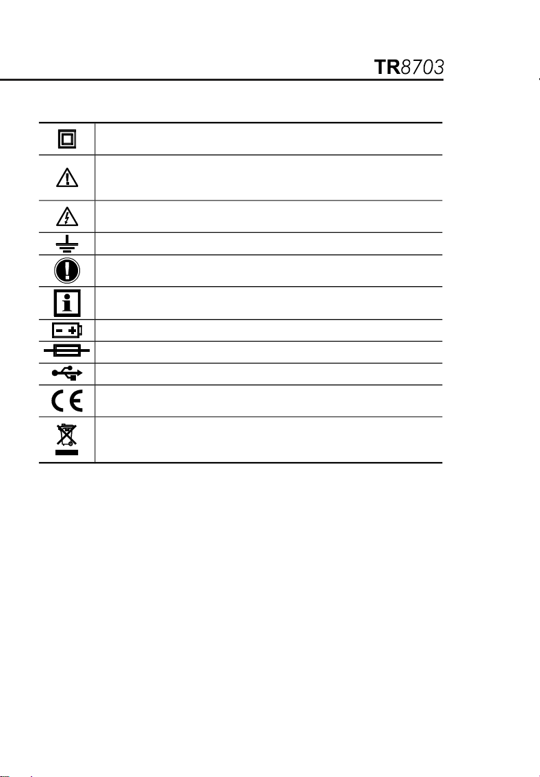
International electrical symbols
Signifies that the instrument is protected by double or reinforced
insulation.
CAUTION Risk of Danger! Indicates a WARNING and that the
operator must refer to the user manual for instructions before
operating the instrument in all cases where this symbol is marked.
Risk of electric shock. The voltage at the parts marked with this
symbol may be dangerous.
Ground/Earth
Important instructions to read and understand completely.
Important information to acknowledge.
Battery.
Fuse.
USB socket.
Compliance with the Low Voltage & Electromagnetic Compatibility
European directives ( 3/23/CEE & 89/336/CEE).
In the European Union, this product is subject to a separate collection
system for recycling electrical and electronic components In
accordance with directive WEEE 2002/96/EC.
Definition of measurement categories
CAT II: For measurements performed on circuits directly connected to the
electrical distribution system. Examples are measurements on household
appliances or portable tools.
CAT III: For measurements performed in the building installation at the
distribution level such as on hardwired equipment in fixed installation and
circuit breakers.
CAT IV: For measurements performed at the primary electrical supply (<1000V)
such as on primary overcurrent protection devices, ripple control units, or
meters.

Receiving Your Shipment
Upon receiving your shipment, make sure that the contents are consistent
with the packing list. Notify your distributor of any missing items. If the
equipment appears to be damaged, file a claim immediately with the
carrier and notify your distributor at once, giving a detailed description of
any damage. Save the damaged packing container to substantiate your
claim.
Ordering Information
TR8703 Digital Transformer Ratiometer
Includes NiMH batteries (installed), 115 V power cord, set of two 15 ft
leads, 10 ft USB cable, external battery charger (90-264 VAC 50/60 Hz),
soft carrying case, software, warranty certified and a user manual.
Accessories and replacement parts
Fuse - set of 5, 0.5 A 250 V (5x20 mm, Slow Blow)
Fuse - set of 5, 4 A 125 V (5x20 mm, Slow Blow)
Lead - Set of 2, 30 ft
Lead - Replacement Set of 2, 15 ft
Battery - Replacement Set of 2, 12 V NiMH rechargeable
Replacement Battery Charger
Replacement USB Cable, 10 ft
8

1. Product features
1.1. Description
The Digital Transformer Ratiometer TR8 03 is a lightweight, rugged,
portable instrument designed for onsite testing of power, potential and
current transformers.
Operation of the TR8 03 is fully automatic. No user calibration, range
selection, hand cranking or tedious balancing is required.
During each test cycle, the TR8703 automatically checks for:
H/X lead reversal
Continuity of tested circuits/windings (if configured)
Short circuit conditions (high current)
Upon completion of a test cycle, the TR8703 displays:
Turns Ratio: The ratio of the primary to secondary voltage at the trans-
former terminals due to test excitation
Excitation Current: The RMS excitation current in the H winding due to
test excitation during negligible loading of the associated X winding
Polarity: Indicates the polarity (phase) of X relative to H
Deviation: Indicates the deviation from nameplate ratio in %
Turns Ratio, Excitation Current, Polarity and Deviation are useful
parameters in diagnosing and predicting a variety of faults that occur in
power, potential and current transformers.
The TR8703 will display the following messages:
Incorrect Lead Connections
H/X Reversal (accidental step-up misconnection)
Short (excess excitation current)
Open Circuits
Circuit Continuity
Low Battery
9

In addition, the TR8 03 allows the user to store the data in automatic or
manual mode after each test eliminating the need to write down the test
results. Each measurement record is date and time stamped providing
complete test information.
The user can also save Nameplate voltages and compare the results as
the data is being gathered. The data can later be downloaded to a PC
and analyzed using the software package which is included with the
product.
The software allows full control of the instrument.
The TR8 03 utilizes an advanced, low-voltage, step-down
measurement technique in which the high voltage “H” windings are
subjected to test excitation. This results in greater operator safety
and the ability to test a much wider array of transformer types and
sizes.
10

1.2. Control features
1. Display: Displays data, status and control features of the instrument.
2. USB Conector: Allows connection to a computer for instrument
configuration set-up and status check, downloading of the stored data
using the software and running a test.
3. High side “H” Cable Connector (primary): Connection for the
primary side of the transformer.
4. Low side “X” Cable Connector (secondary): Connection for the
secondary side of the transformer.
5. Battery Charge Input Connector: Allows the smart charger to
charge the batteries.
6. Power Switch: Turns the instrument ON or OFF (if the charger is not
connected). If the charger is connected, the batteries charge in
OFF/CHARGE position.
7. Operation and Battery Low Indicator: Green LED indicates that the
instrument is on and blinks when the batteries are getting low (<12 V).
The instrument will completely shut down when the batteries are
below 8. V.
11
Indice
Lingue:
Altri manuali MEGABRAS Strumento di misura


