Sonic Driver FIXED-UFM Manuale utente
Made in Britain
FIXED-UFM Ultrasonic Flowmeter
Installation Manual
Version 4.0
13th March 2023
Copyright Sonic Driver Ltd 2023

Contents
1.0 Introduction
•1.1 Transit Time Measurement
•1.2 Packing List
•1.3 General Precautions
•1.4 Cleaning
•1.5 Connecting the Flow Transducers
•1.6 Mounting the Flow Transducers
•1.7 Mounting the UFM
•1.8 Wiring the UFM
•1.9 Turning the UFM On
2.0 Using the Quick Start Sequence
•2.1 Transducer Menu
•2.1.1 Type
•2.1.2 Mounting
•2.2 Pipe Menu
•2.2.1 Outer Diameter
•2.2.2 Wall Thickness
•2.2.3 Material
•2.2.4 Sound Velocity
•2.3 Liner Menu
•2.3.1 Material
•2.3.2 Sound Velocity
•2.3.3 Thickness
•2.4 Fluid Menu
•2.4.1 Type
•2.4.2 Temperature
3.0 Sensor Positioning
•3.1 Optimising Transducer Mounting Location
•3.2 Upstream and Downstream Pipe Runs
•3.3 Transducer Mounting
•3.4 Transducer Spacing
4.0 Heat Metering
5.0 Error Codes
6.0 Icons
7.0 Specification
8.0 Product Identification
9.0 Service
10.0 Limited Warranty and Disclaimer

Appendix A Contact Details
Appendix B Table of fluid properties
Appendix C Table of pipe and lining material properties
Appendix D Table of speed of sound in water
Appendix E Table of typical pipe roughness values
1.0 Introduction
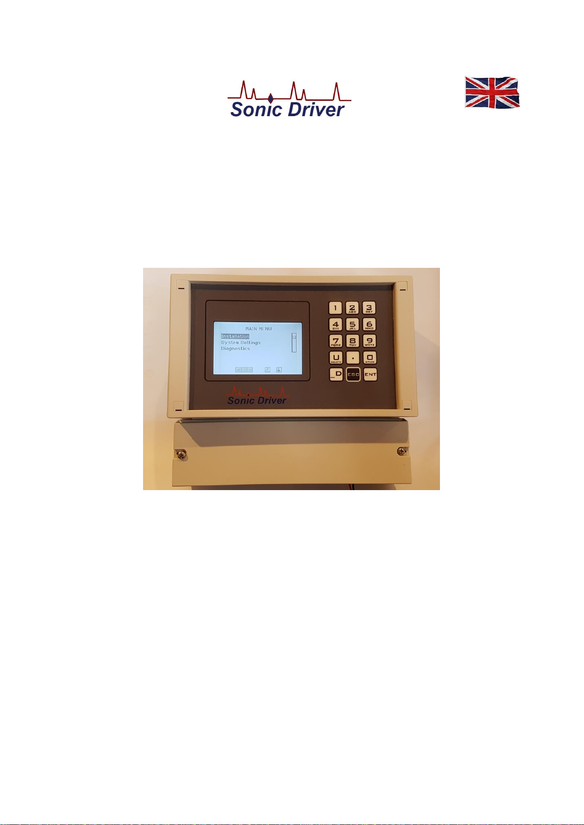
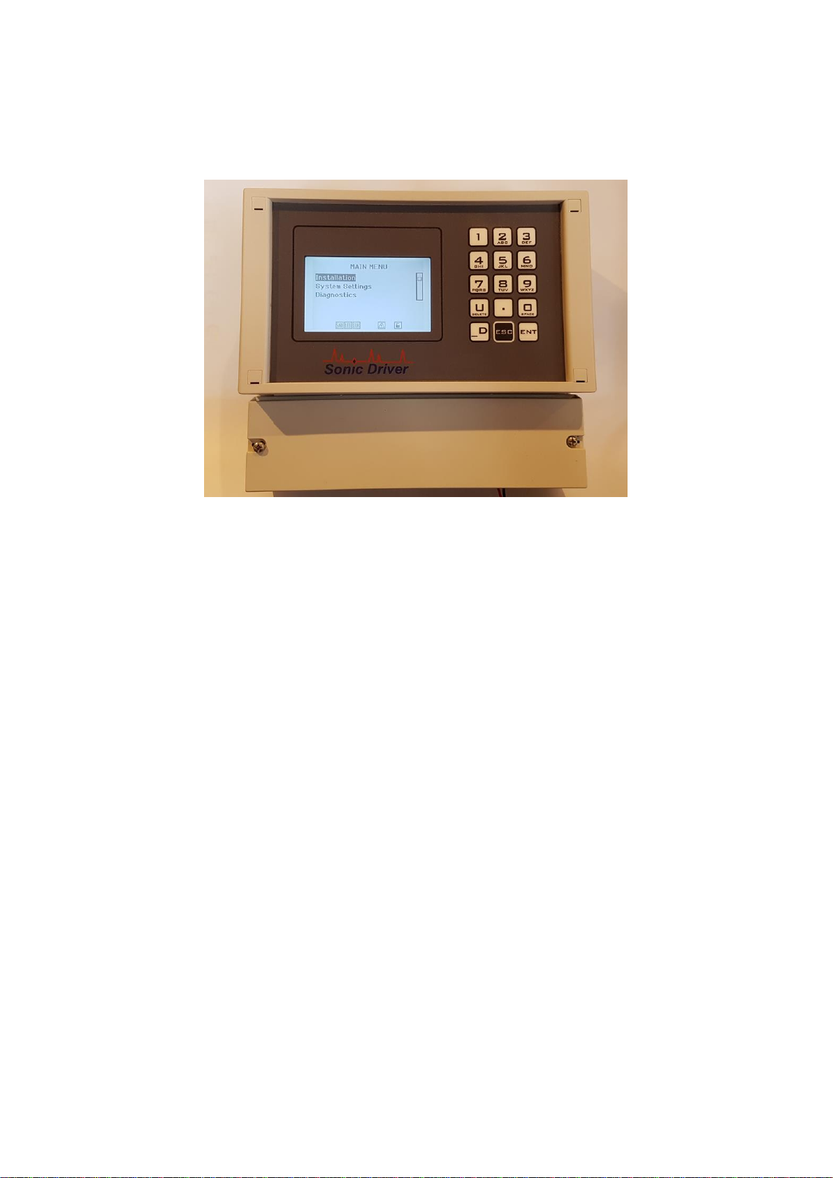
Congratulations on choosing the Sonic Driver FIXED-UFM clamp-on ultrasonic flowmeter,
figure(1).
Figure(1) The Sonic Driver FIXED-UFM.
The ultrasonic flowmeter (UFM) uses advanced Digital Signal Processing (DSP) and transit time
measurement techniques (Sonic Driver TM) to make accurate and reliable clamp-on ultrasonic flow
velocity measurements on liquids flowing in closed pipes
Using information about the installation, entered by the user, using the meters intuitive and easy to
us menu driven User Interface (UI) the UFM can display;
•Flow velocity
•Volumetric flow rate
•Mass flow rate
•Heat quantity flow rate
When making heat measurements the UFM uses the calculation method outlined in EN1434-1
section 8 and its appendix A.
The UFM comes in 3 different versions;
•Standard - outer pipe diameter ranged 10.0 to 115.0mm
•Medium - outer pipe diameter ranged 115.0 to 225.0mm
•Large - outer pipe diameter ranged 225.0 to 6500.0mm
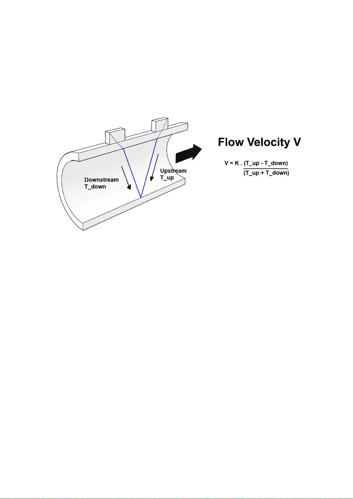
1.1 Transit Time Measurement
The principle of flow measurement using ultrasonic clamp-on transit time measurement is simple,
see figure(2).
Figure(2) The principle of transit time flow measurement.
Two ultrasonic transducers are coupled or clamped to the outside of the pipe at a predetermined
distance apart.
Ultrasonic pulses travel between the transducers through the pipe wall and the fluid within the pipe.
If the fluid is flowing then it takes slightly longer for the ultrasound to travel against the flow
(upstream time T_up) than with the flow (downstream time T_down), see figure(2).
In a typical installation the individual times measured upstream and downstream are just a few
hundred microseconds, the difference between them is typically measured in tens of nanoseconds.
This very small time difference (T_up - T_down) is measured by the UFM and is directly
proportional to the flow velocity (V) of the fluid.
Knowing the pipe internal cross-sectional area the UFM can calculate volumetric flow rate in many
common engineering units. A further knowledge of the density of the fluid allows the UFM to
calculate mass flow rate.
Finally, a knowledge of inlet and outlet fluid temperature and Specific Heat Capacity of the fluid
allows the UFM to calculate heat flow rate.
All of these rates can be totalled and positive, negative and net values displayed.

1.2 Packing List
Within the UFM packaging you should find;
Item
Quantity
FIXED-UFM
1
PEEK/Stainless Steel Flow Transducer
2
Chain Mounting Clamp
2
Tape Measure
1
Coupling Gel
1
Table(1) Packing List.
If any item on the packing list is missing or has been damaged in transit contact Service, see
Appendix A.
1.3 General Precautions
The content of this manual has been carefully checked and is believed to be accurate.
Sonic Driver Ltd assumes no responsibility for any inaccuracies that may be contained in this
manual.
In no event will Sonic Driver be liable for direct, indirect, special, incidental or consequential
damages resulting from any defect or omission in this manual, even if we are advised of the
possibility of such damages.
Sonic Driver Ltd reserves the right to make improvements to its manuals, instructions and products
at any time, without notice or obligation. The latest revisions may be found on the company web
site, see appendix A.
The UFM is a precision measuring instrument and should be handled and operated with care;
•Before operating the UFM for the first time read the installation manual and operating
instruction fully.
•Only use the UFM in the way and for the purpose that it is intended.
•Do not subject the UFM to bumps and shocks such as caused by dropping the UFM.
•Keep the UFM and its transducers and probes clean.
•Only use the UFM within its ambient temperature and stated level of Ingress Protection.
•Avoid excessive stress and bending of transducer cables and connectors.
•Avoid striking the clear display window and keypad with sharp objects.
1.4 Cleaning
Wipe the UFM and sensors with tissue or soft cloth after use, remove excess coupling gel.
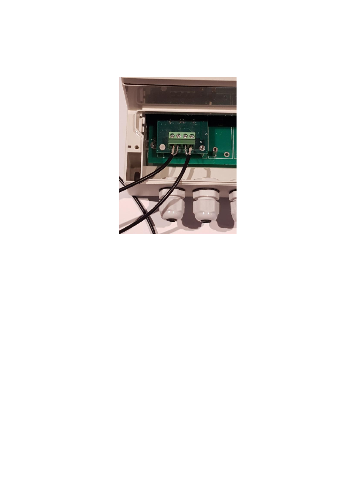
1.5 Connecting the Flow Transducers
Connect the flow transducers to the screw terminal connectors in the screw terminal compartment
of the UFM, see figure(3).
Figure(3) Flow transducer connection.
The left-hand screw terminals connect the flow transducer which is mounted on the pipe
downstream, the right-hand screw terminals connect the flow transducer which is mounted
upstream.
1.6 Mounting the Flow Transducers
Mount the flow transducers on the pipe using the chain clamps supplied, see figure(4). Ensure that
the arrow on the labels (arrowhead and flights) on the flow transducers is pointing in the direction
of flow.
Use coupling gel between the transducers and the pipe to give good ultrasonic contact.
Measure the spacing of the transducers using the tape measure provided, note that spacing is
measured between the front faces of the transducers. Ensure the transducers are facing each other
and aligned axially along the pipe.
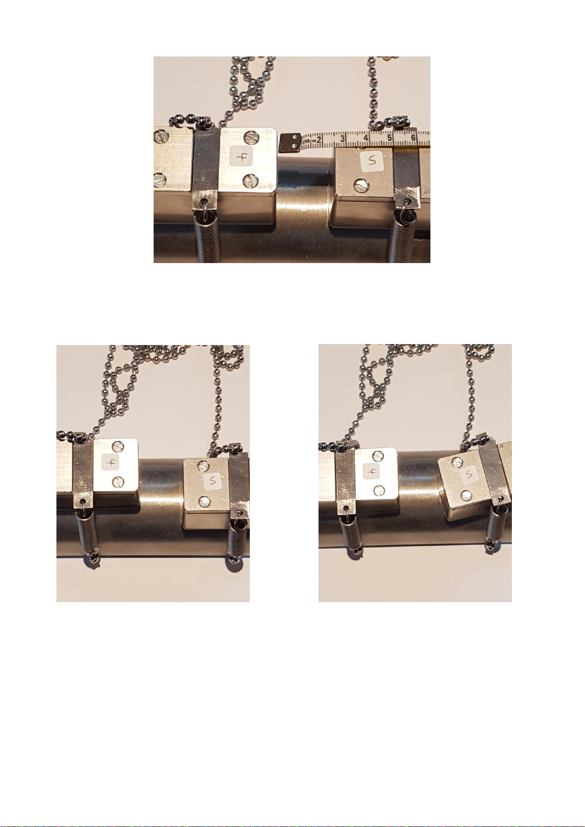
Figure(4) Flow transducer mounting, spacing is 25mm between front faces.
In figure(5) and figure(6) the transducers are misaligned and twisted, as a result the UFM will make
poor flow measurements.
Figure(5) Misaligned transducers. Figure(6) Twisted transducers.
1.7 Mounting the UFM
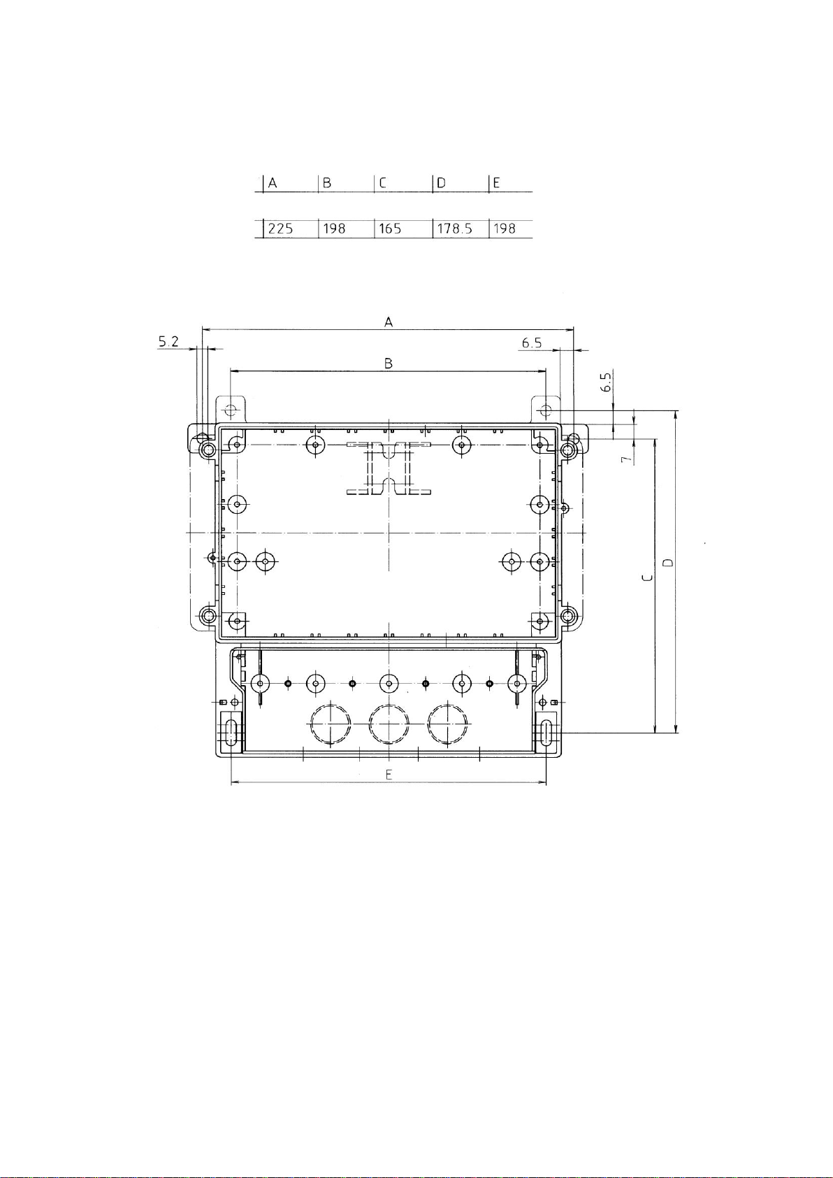
When wall mounting the UFM refer to Figure(7),
Figure(7) Wall mounting the UFM.
1.8 Wiring the UFM
To power on the UFM simply apply AC or DC power as appropriate to the model.
Always disconnect the mains supply before removing any covers and connecting any external
wiring to the UFM. Only qualified Electricians should install the UFM and IET BS7671:2008
wiring regulations must be adhered to.
Always install a ground fault interrupt circuit (GFIC)/residual current circuit breaker (RCCB) with
a maximum trigger current of 30 mA.
If installed outside, provide over voltage protection through an MCB rated not greater than 5 Amps.

With fixed wiring, a disconnecting device (local interruption) must be integrated into the power
supply line. The disconnecting device must meet BS7671:2008 standards and regulations. It must
be installed near the device, be able to be reached easily by the operator and labelled as a
disconnecting device.
1.9 Turning the UFM On
To power on the UFM simply apply AC or DC power as appropriate to the model.
As soon as the UFM is switched on a self-diagnostic program will start. If an error is detected an
error message will be displayed prompting user action. If the error persists, contact customer
support.
See relevant sections on Input/Output and Datalogger below for more detail of what tests are carried
out.
Error codes and their meanings can be found in the Diagnostics Menu.
Altri manuali per FIXED-UFM
1
Indice
Altri manuali Sonic Driver Strumento di misura


