WIKA TR30 Manuale utente

E
F
D
GB
Operating instructions
Betriebsanleitung
Mode d'emploi
Manual de instrucciones
Model TR30
with circular connector
Resistance thermometer, compact design, model TR30
Resistance thermometer, miniature design, model TR31
Widerstandsthermometer, Kompaktausführung, Typ TR30
Widerstandsthermometer, Miniaturausführung, Typ TR31
Sonde à résistance, exécution compacte, type TR30
Sonde à résistance, exécution miniature, type TR31
Térmómetro de resistencia, en versión compacta, modelo TR30
Térmómetro de resistencia, ejecución en miniatura, modelo TR31
Model TR30
with angular connector
Model TR31

2 WIKA operating instructions models TR30, TR31
11377551.05 06/2012 GB/D/F/E
E
F
D
GB Operating instructions models TR30, TR31
Page 3 - 24
Betriebsanleitung Typen TR30, TR31
Seite 25 - 44
Mode d'emploi types TR30, TR31
Page 45 - 66
Manual de instrucciones modelos TR30, TR31
Página 67 - 86
© 2010 WIKA Alexander Wiegand SE & Co. KG
All rights reserved. / Alle Rechte vorbehalten.
WIKA® is a registered trademark in various countries.
WIKA® ist eine geschützte Marke in verschiedenen Ländern.
Prior to starting any work, read the operating instructions!
Keep for later use!
Vor Beginn aller Arbeiten Betriebsanleitung lesen!
Zum späteren Gebrauch aufbewahren!
Lire le mode d'emploi avant de commencer toute opération !
A conserver pour une utilisation ultérieure !
¡Leer el manual de instrucciones antes de comenzar cualquier trabajo!
¡Guardar el manual para una eventual consulta!

11377551.05 06/2012 GB/D/F/E
WIKA operating instructions models TR30, TR31 3
GB
1. General information 4
2. Safety 5
3. Specications 8
4. Design and function 12
5. Transport, packaging and storage 15
6. Commissioning, operation 15
7. Conguration of models TR30-W, TR31-W 18
8. Connecting PU-448 programming unit 20
10. Maintenance and cleaning 21
12. Dismounting, return and disposal 21
Appendix 1: EC-declaration of conformity model TR30 23
Appendix 2: EC-declaration of conformity model TR31 24
Contents
Contents
Declarations of conformity can be found online at www.wika.com.
11377551.05 06/2012 GB/D/F/E
4 WIKA operating instructions models TR30, TR31
GB
1. General information
■
The resistance thermometer described in the operating instructions has been designed
and manufactured using state-of-the-art technology. All components are subject to
stringent quality and environmental criteria during production. Our management systems
are certied to ISO 9001 and ISO 14001.
■
These operating instructions contain important information on handling the instrument.
Working safely requires that all safety instructions and work instructions are observed.
■
Observe the relevant local accident prevention regulations and general safety
regulations for the instrument's range of use.
■
The operating instructions are part of the product and must be kept in the immediate
vicinity of the instrument and readily accessible to skilled personnel at any time.
■
Skilled personnel must have carefully read and understood the operating instructions
prior to beginning any work.
■
The manufacturer's liability is void in the case of any damage caused by using the
product contrary to its intended use, non-compliance with these operating instructions,
assignment of insuciently qualied skilled personnel or unauthorised modications to
the instrument.
■
The general terms and conditions contained in the sales documentation shall apply.
■
Subject to technical modications.
■
Further information:
- Internet address: www.wika.de / www.wika.com
- Relevant data sheet: TE 60.30, TE 60.31
- Application consultant: Tel.: (+49) 9372/132-0
E-Mail: [email protected]
Explanation of symbols
WARNING!
... indicates a potentially dangerous situation that can result in serious injury or
death, if not avoided.
CAUTION!
... indicates a potentially dangerous situation that can result in light injuries or
damage to equipment or the environment, if not avoided.
Information
… points out useful tips, recommendations and information for ecient and
trouble-free operation.
1. General information
11377551.05 06/2012 GB/D/F/E
WIKA operating instructions models TR30, TR31 5
GB
DANGER!
...identies hazards caused by electrical power. Should the safety instructions
not be observed, there is a risk of serious or fatal injury.
WARNING!
... indicates a potentially dangerous situation that can result in burns, caused
by hot surfaces or liquids, if not avoided.
Abbreviations
RTD "Resistance temperature detector"
TC "Thermocouple"
2. Safety
WARNING!
Before installation, commissioning and operation, ensure that the appropriate
resistance thermometer has been selected in terms of measuring range,
design, specic measuring conditions and appropriate wetted parts' materials
(corrosion).
Non-observance can result in serious injury and/or damage to the equipment.
Further important safety instructions can be found in the individual chapters of
these operating instructions.
2.1 Intended use
Model TR30 and TR31 resistance thermometers are used as general-purpose thermometers
for the measurement of temperatures from -50 … +150 °C (without neck tube) and
-50 … +250 °C (with neck tube) in liquid and gaseous media. They can be used for pressures
up to 40 bar (special designs to 400 bar dependent on insertion length and diameter).
The instrument has been designed and built solely for the intended use described here,
and may only be used accordingly.
The technical specications contained in these operating instructions must be observed.
Improper handling or operation of the instrument outside of its technical specications
requires the instrument to be taken out of service immediately and inspected by an
authorised WIKA service engineer.
1. General information / 2. Safety

11377551.05 06/2012 GB/D/F/E
6 WIKA operating instructions models TR30, TR31
GB
If the instrument is transported from a cold into a warm environment, the formation of
condensation may result in the instrument malfunctioning. Before putting it back into
operation, wait for the instrument temperature and the room temperature to equalise.
The manufacturer shall not be liable for claims of any type based on operation contrary to
the intended use.
2.2 Personnel qualication
WARNING!
Risk of injury if qualication is insucient!
Improper handling can result in considerable injury and damage to equipment.
■
The activities described in these operating instructions may only be carried
out by skilled personnel who have the qualications described below.
■
Keep unqualied personnel away from hazardous areas.
Skilled personnel
Skilled personnel are understood to be personnel who, based on their technical training,
knowledge of measurement and control technology and on their experience and
knowledge of country-specic regulations, current standards and directives, are capable of
carrying out the work described and independently recognising potential hazards.
Special operating conditions require further appropriate knowledge, e.g. of aggressive
media.
2.3
Special hazards
WARNING!
For hazardous media such as oxygen, acetylene, ammable or toxic gases or
liquids, and refrigeration plants, compressors, etc., in addition to all standard
regulations, the appropriate existing codes or regulations must also be
followed.
WARNING!
Protection from electrostatic discharge (ESD) required.
The proper use of grounded work surfaces and personal wrist straps is
required when working with exposed circuitry (printed circuit boards),
in order to prevent static discharge from damaging sensitive electronic
components.
2. Safety
11377551.05 06/2012 GB/D/F/E
WIKA operating instructions models TR30, TR31 7
GB
To ensure safe working on the instrument, the operating company must ensure
■
that suitable rst-aid equipment is available and aid is provided whenever
required,
■
that the operating personnel are regularly instructed in all topics regarding
work safety, rst aid and environmental protection, and know the operating
instructions, in particular the section on safety instructions.
DANGER!
Danger of death caused by electric current
Upon contact with live parts, there is a direct danger of death.
■
The instrument may only be installed and mounted by skilled personnel.
■
Operation using a defective power supply unit (e.g. short circuit from the
mains voltage to the output voltage) can result in life-threatening voltages at
the instrument!
WARNING!
Residual media in dismounted instruments can result in a risk to personnel, the
environment and equipment.
Take sucient precautionary measures.
Do not use this instrument in safety or Emergency Stop devices. Incorrect use
of the instrument can result in injury.
Should a failure occur, aggressive media with extremely high temperature and
under high pressure or vacuum may be present at the instrument.
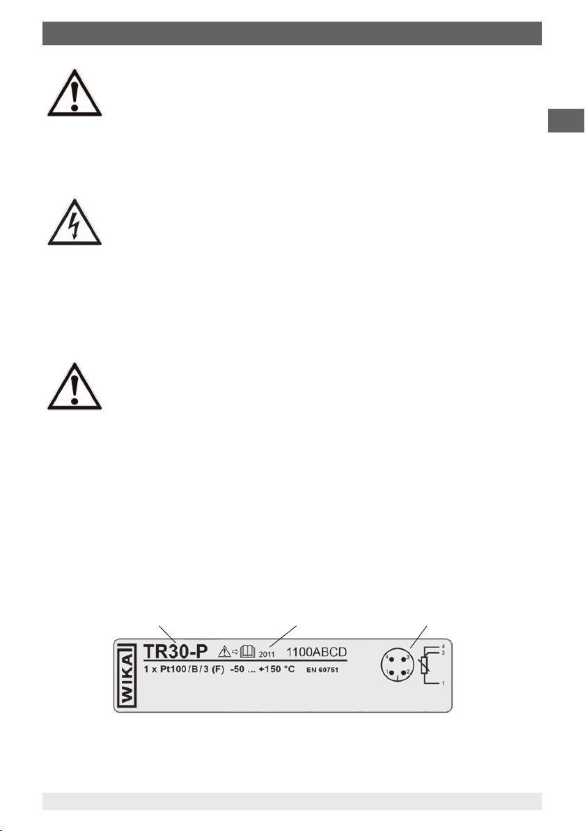
2.4 Labelling, safety marks
Product labels
■
Resistance thermometer model TR30
2. Safety
Model Electrical connectionYear of manufacture

11377551.05 06/2012 GB/D/F/E
8 WIKA operating instructions models TR30, TR31
GB
Explanation of symbols
Before mounting and commissioning the instrument, ensure you read
the operating instructions!
CE, Communauté Européenne
Instruments bearing this mark comply with the relevant European directives.
3. Specications
3.1 Resistance thermometer model TR30
■
Output signal Pt100, model TR30-P
Measuring element and measuring insert
The Pt100 measuring element is located in the thermometer's probe tip.
Output signal Pt100, model TR30-P
Temperature range Measuring range without neck tube -50 ... +150 °C, with neck tube -50 ... +250 °C
Measuring element Pt100 (measuring current: 0.1 ... 1.0 mA)
Connection method 2-wire
3-wire
4-wire
Sensor tolerance value 1)
per DIN EN 60751
Class B
Class A
Electrical connection Angular DIN connector Form A, M12 x 1 circular connector, 4-pin
Readings in % refer to the measuring span
For a correct determination of the overall measuring error, both sensor and transmitter measuring deviations have to
be considered.
1) For detailed specications for Pt100 sensors, see Technical Information IN 00.17 at www.wika.com.
■
Resistance thermometer model TR31
2. Safety / 3. Specications
Model Electrical connectionYear of manufacture

11377551.05 06/2012 GB/D/F/E
WIKA operating instructions models TR30, TR31 9
GB
3. Specications
■
Output signal 4 ... 20 mA, model TR30-W
Measuring element and measuring insert
The Pt100 measuring element is located in the thermometer's probe tip.
The 4 ... 20 mA transmitter is mounted and potted within the tubular body of the
thermometer.
Output signal 4 ... 20 mA, model TR30-W
Temperature range Measuring range without neck tube -50 ... +150 °C,
with neck tube -50 ... +250 °C 2)
Measuring element Pt100 (measuring current: 0.5 mA)
Sensor tolerance value 1)
per DIN EN 60751
Class B
Measuring span minimum 20 K, maximum 300 K
Basic conguration Measuring range 0 ... 150 °C, other measuring ranges are adjustable
Analogue output 4 ... 20 mA, 2-wire
Measuring error
per DIN EN 60770, 23 °C ±5 K
0.2 % (Transmitter) 3)
Linearisation linear with temperature per DIN EN 60751
Linearisation error ±0.1 % 4)
Switch-on delay, electrical < 10 ms
Signalling of sensor burnout congurable: NAMUR downscale < 3.6 mA (typically 3 mA)
NAMUR upscale > 21.0 mA (typically 23 mA)
Sensor short-circuit
not congurable, generally NAMUR downscale < 3.6 mA (typ. 3 mA)
Load RARA ≤ (UB - 9 V) / 0.023 A with RA in Ω and UB in V
Eect of load ± 0.05 % / 100 Ω
Power supply DC 10 ... 35 V
Max. permissible residual ripple 10 % at 24 V / maximum 300 Ω Load
Power supply input protected against reverse polarity
Power supply eect ± 0.025 % / V
Electromagnetic compatibility
(EMC)
2004/108/EC, DIN EN 61326 emission (Group 1, Class B) and immunity
(industrial application) 5), and also per NAMUR NE21
Temperature units congurable °C, °F, K
Info data TAG No., descriptor and message can be stored in transmitter
Conguration and calibration data
permanently stored in EEPROM
Electrical connection Angular DIN connector Form A, M12 x 1 circular connector, 4-pin
Readings in % refer to the measuring span
For a correct determination of the overall measuring error, both sensor and transmitter measuring deviations have to
be considered.
1) For detailed specications for Pt100 sensors, see Technical Information IN 00.17 at www.wika.com.
2) The temperature transmitter should therefore be protected from temperatures over 85 °C
3) For measuring spans smaller than 50 K additional 0.1 K
4) ±0.2 % for measuring ranges with a lower limit less than 0 °C
5) Use resistance thermometers with shielded cable, and ground the shield on at least one end of the lead, if the cables are longer than
30 m or leave the building.

11377551.05 06/2012 GB/D/F/E
10 WIKA operating instructions models TR30, TR31
GB
The permissible load depends on
the loop supply voltage.
Voltage UB in V
Load RA in Ω
0 10 24 30 36
1182
909
636
Load diagram
3. Specications
For setting the measuring range see chapter 7 "Conguration of models TR30-W and
TR31-W".
■
Output signal 0 ... 10 V, model TR30-V
Measuring element and measuring insert
The Pt100 measuring element is located in the thermometer‘s probe tip.
The 0 … 10 V transmitter is mounted in the tubular body of the thermometer.
Output signal 0 ... 10 V, model TR30-V
Temperature range Measuring range without neck tube -50 ... +150 °C,
with neck tube -50 ... +200 °C 2), measuring ranges are not adjustable
Measuring element Pt100 (measuring current: 0.5 mA)
Sensor tolerance value 1)
per DIN EN 60751
Class B
Measuring span minimum 50 K, maximum 250 K
Basic conguration Measuring range 0 ... 100 °C
Measuring ranges -50 ... +50, 0 ... 50, 0 ... 80, 0 ... 100, 0 ... 120, 0 ... 150, 0 ... 200 °C
Analogue output 0 ... 10 V, 3-wire
Overall measuring error 3) < 0.5 % of span
Power supply DC 12 ... 30 V
Max. permissible residual ripple 10 %
Electromagnetic compatibility
(EMC)
2004/108/EC, EN 61326 emission (Group 1, Class B) and interference
immunity (industrial application) 4)
Electrical connection Angular DIN connector Form A, M12 x 1 circular connector, 4-pin
Readings in % refer to the measuring span
For a correct determination of the overall measuring error, both sensor and transmitter measuring deviations have to
be considered.
1) For detailed specications for Pt100 sensors, see Technical Information IN 00.17 at www.wika.com.
2) The temperature transmitter should therefore be protected from temperatures over 85 °C
3) For measuring spans smaller than 50 K additional 0.1 K
4) Use resistance thermometers with shielded cable, and ground the shield on at least one end of the lead, if the cables are longer than
30 m or leave the building.
For further specications on the TR30 see WIKA data sheet TE 60.30.
Altri manuali per TR30
1
Questo manuale è adatto per i seguenti modelli
2
Indice
Lingue:
Altri manuali WIKA Termometro

WIKA
WIKA 70 Manuale utente

WIKA
WIKA CTH7000 Manuale utente

WIKA
WIKA CTH6300 Manuale utente

WIKA
WIKA Twin-Temp 54 Manuale utente

WIKA
WIKA TR12 Series Manuale utente

WIKA
WIKA 53 Series Manuale utente

WIKA
WIKA R52.100 Manuale utente

WIKA
WIKA TGS55 Manuale utente

WIKA
WIKA CTR3000 Manuale utente

WIKA
WIKA CTH6500 Manuale utente

WIKA
WIKA TR36 Manuale utente

WIKA
WIKA TR30 Manuale utente

WIKA
WIKA TR33 Manuale utente

WIKA
WIKA CTH 6200 Manuale utente

WIKA
WIKA TG53 Manuale utente

WIKA
WIKA TG58SA Istruzioni operative

WIKA
WIKA TR Series Manuale utente

WIKA
WIKA 55 Series Manuale utente

WIKA
WIKA TR25 Manuale utente

WIKA
WIKA TR33 Manuale utente


