TM-G84-LS Rev: GDCR# 15-0407 DATE: 4/30/15 Federal Identification Code: 11815 © 2015 Cherry Aerospace
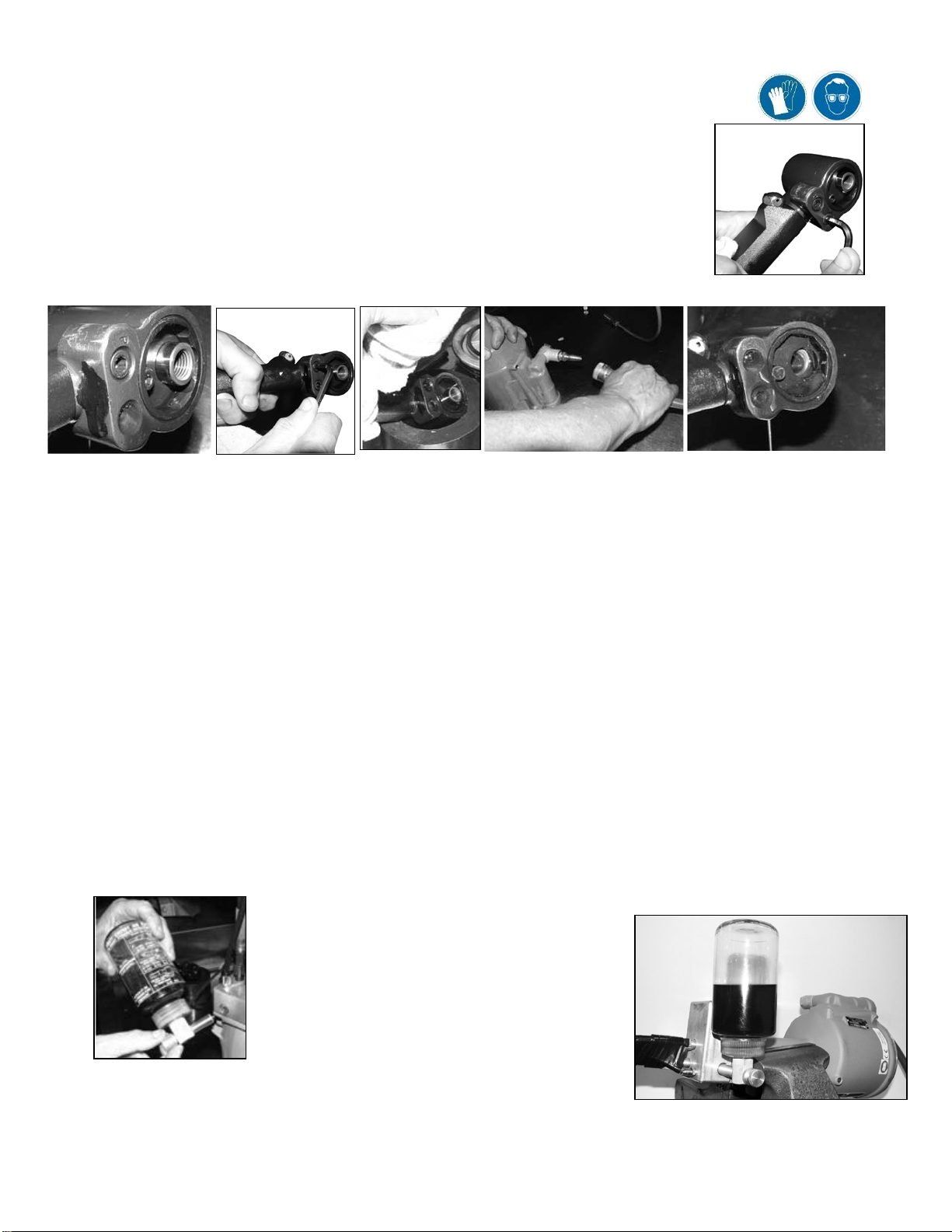
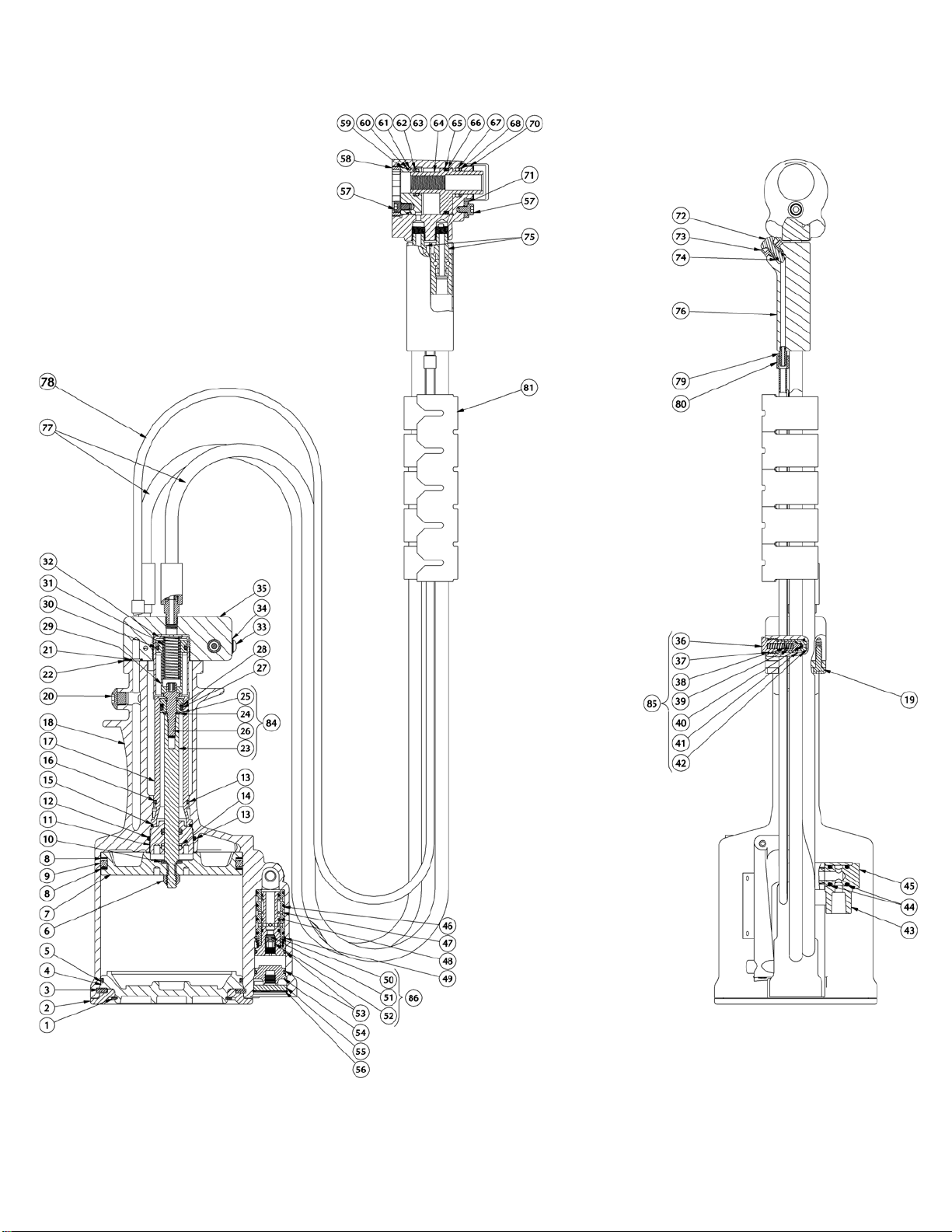
HEAD CYLINDER SUB-ASSEMBLY (744-202)
Caution: Remove Pulling Heads or other attachments before attempting to disassemble.
Disassembly instructions:
•Remove screw (57) and unscrewlock ring (58) with spanner wrench 530-202.
•Drain the fluid over an oil pan; dispose according to environmental regulations.
•Remove rear stop (59) and piston (63) bypressing them out of the rear of thesubassembly.
•Remove seals (60,61, 62, 63, 65, 66, 67 & 68) carefully using a bent hook tool.
Assembly instructions:
•Inspect all components to make sure allsurfaces are clean and free of burrs.
•Install O-ring and back-up ring (67 & 68) intogroove of head cylinder (70).
•Thread seal guides 744-194 & 744-195 on both sides of the piston (64).
•Mount O-ring and back-up ring (65 &66) onto the piston (64).
•Carefully push/twist piston (64) into the head cylinder (70)bore, pressing it all the wayin.
•Assemble O-ring, backup ring (60 & 61) and O-ring, Back-up ring (62&63) onto rear stop (59) and carefully press itinto
the head cylinder.
•Thread-in lock ring (58) using spanner wrench 530-202 and secure it with screw(57); use
Loctite® 242 on threads. Remove seal guides.
Swivel Assembly Instructions:
•Apply Loctite 545 on the male threads of swivel (75).
•Thread swivel (75) into head cylinder (70) and thread until hand tight.
•Using a 7/16 wrench, tighten threads byrotating one full turn from initial thread seating to secure
in place –Do not over tighten.
•Allow Loctite tocure for 24 hoursfor full strength.
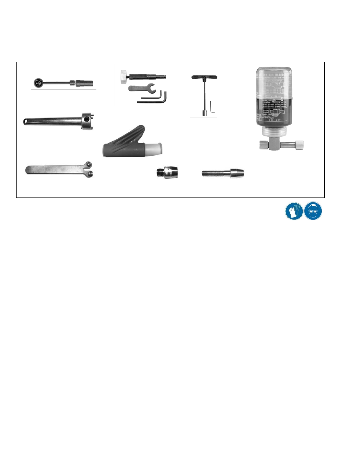
HANDLE SUB-ASSEMBLY (744-189)
Disassembly Instructions: Make sure that the air supply is disconnected before proceeding.
•Unscrew cap screws (19) and remove manifold (35);
•Drain the fluid completelyinto a pan and dispose according to environmental regulations.
•Remove gasket (22)and O-rings (21)
•Remove retaining ring (1) andthe base cover (2) from the bottom of the unit.
•Remove retaining ring (3) andcarefully pry handlebase (4) from the bottom of the unit,using a screwdriver.
•Engage wrench 700A61 into thehex socket of the piston rod cap (26).
•Remove locknut (6)with a ½ inch (13 mm)socket, while holding with the wrench; unscrew air piston (7) by using wrench 530-
201 and a 1 inch (26mm) socket.
•Pull the air piston (7) out through the bottom of the unitwith the help of the tool P1178.
•Remove power piston subassembly (84)through the top of the handle (18) using the guide tool 744-104.
•Remove the packing plug (11) with the help of wrench 530-201 and a 1 ¼inch (32 mm) Socket.
•Note: To loosenit, hold the handle upside down in a vise, if necessary.
•Remove the O-rings (12 and13) and back-up rings (14) with a thin, bent hook.
•Place an 1 inch (25,4 mm) rod ontop of power cylinder (17) and tap it out carefully through the bottom of the unit with a mallet.
Assembly Instructions: Lubricate O-rings with Parker®silicone O-ring lube or equivalent and handle all seals with care.
•Make sure the gaskets andseals are in good condition and are placed correctly.
•Insert the power cylinder (17) with O-rings (15 & 16) into the handle (18) bore through the bottom of handle. To properly seat it,
place an 1 inch (26 mm) bar against its bottom surface, and carefully tap into place with a mallet.
•Insert O-rings (13) and back-up rings (14)in packing plug (11).
•Thread packing plug in tightly against the power cylinder (17)usingwrench 530-201 and a 1 ¼ inch (32 mm) socket.
•Thread seal guide tool 744-104 into the end of the power piston (25) then push into the bore of the power cylinder (17) through
the top of handle (18). Tap it though the packing plug (11) with a mallet; remove theseal guide.
•Using wrench 530-201 insertair piston (7) with quad ring (9) and back-up rings (8) into themain bore of the handle (18) until it
engages the threaded end of the power piston (25); tighten them together wrench 700A61.
•Thread and tighten locknut (6) onto power piston (25) with a ½” socket (13 mm) at 50 to 59 in-lbs (5,65 to 6,67 N-
m).
•Insert handlebase (4) with lubricated O-ring (5) into thebottom of the handle (18) and tap it into its seat.
•Place retaining ring (3), base cover (2), and retaining ring (1).
•Push the piston downwards with the help of wrench 700A61.
•Fill the handle subassemblywith fluid to about1/8 inch (3 mm) above the top of the power piston(17).
•Place new gasket & O-rings (21,22) on topof handle (18); mountthe manifold (35) tightening screws (19) evenly.
8