Glas Craft GCP2RA Manuale utente

Probler P2
Dispense Gun
For use with non-ammable foam and polyurea.
Not for use in explosive atmospheres.
90-110 psi (0.62-0.76 MPa, 6.2-7.6 bar) Air Inlet Pressure Range
3500 psi (24.1 MPa, 241 bar) Maximum Static Fluid Pressure
USER MANUAL
Important Safety Instructions
Read all warnings and instructions in
this manual. Save these instructions.
Models:
GCP2RA
GCP2R0
GCP2R1
GCP2R2
GCP2R3
GCP2R4
GCP2R5
ti19826a

Table Of Contents
Section 1 Installation
Warnings ............................................................................................................................................................ 3
Introduction ........................................................................................................................................................ 7
Standard Equipment .......................................................................................................................................... 8
Translations ........................................................................................................................................................ 8
Equipment Assembly ......................................................................................................................................... 9
Section 2 Operation
Start-up Instructions ........................................................................................................................................... 11
Section 3 General Information
Assembly Drawings ............................................................................................................................................. 13
Maintenance ........................................................................................................................................................ 15
Options ................................................................................................................................................................ 20
Section 4 Warranty and Reference Information
Graco Warranty .................................................................................................................................................. 26
Technical Assistance ........................................................................................................................................... 27
For Your Reference ............................................................................................................................................. 28
2
Warnings
The following warnings are for the setup, use, grounding, maintenance, and repair of this equipment. The exclamation
point symbol alerts you to a general warning and the hazard symbol refers to procedure-specic risk. Refer back to these
warnings. Additional, product-specic warnings may be found throughout the body of this manual where applicable.
3
WARNING
TOXIC FLUID OR FUMES HAZARD
Toxic uids or fumes can cause serious injury or death if splashed in the eyes or on skin, inhaled, or swal-
lowed.
Read MSDS’s to know the specic hazards of the uids you are using.•
Store hazardous uid in approved containers, and dispose of it according to applicable guidelines.•
Always wear impervious gloves when spraying or cleaning equipment.•
PERSONAL PROTECTIVE EQUIPMENT
You must wear appropriate protective equipment when operating, servicing, or when in the operating area of
the equipment to help protect you from serious injury, including eye injury, inhalation of toxic fumes, burns,
and hearing loss. This equipment includes but is not limited to:
Protective eyewear•
Clothing and respirator as recommended by the uid and solvent manufacturer•
Gloves•
Hearing protection•
SKIN INJECTION HAZARD
High-pressure uid from gun, hose leaks, or ruptured components will pierce skin. This may look like just a
cut, but it is a serious injury that can result in amputation. Get immediate surgical treatment.
Do not point gun at anyone or at any part of the body.•
Do not put your hand over the spray tip.•
Do not stop or deect leaks with your hand, body, glove, or rag.•
Close material shutoff valves and shutoff or disconnect air supply when not spraying.•
Follow Pressure Relief Procedure in this manual, when you stop spraying and before cleaning, checking, •
or servicing equipment.
BURN HAZARD
Equipment surfaces and uid that’s heated can become very hot during operation. To avoid severe burns, do
not touch hot uid or equipment. Wait until equipment/uid has cooled completely.
FIRE AND EXPLOSION HAZARD
Flammable fumes, such as solvent and paint fumes, in work area can ignite or explode. To help prevent re
and explosion:
Use equipment only in well ventilated area.•
Eliminate all ignition sources; such as pilot lights, cigarettes, portable electric lamps, and plastic drop•
cloths (potential static arc).
Keep work area free of debris, including solvent, rags and gasoline.•
Do not plug or unplug power cords, or turn power or light switches on or off when ammable fumes are •
present.
Ground all equipment in the work area.•
Use only grounded hoses.•
Hold gun rmly to side of grounded pail when triggering into pail.•
If there is static sparking or you feel a shock, stop operation immediately. Do not use equipment until •
you identify and correct the problem.
Keep a working re extinguisher in the work area.•
WARNING
EQUIPMENT MISUSE HAZARD
Misuse can cause death or serious injury.
Do not operate the unit when fatigued or under the inuence of drugs or alcohol.•
Do not exceed the maximum working pressure or temperature rating of the lowest rated system compo-•
nent. See Technical Data in all equipment manuals.
Use uids and solvents that are compatible with equipment wetted parts. See Technical Data in all •
equipment manuals. Read uid and solvent manufacturer’s warnings. For complete information about
your material, request MSDS forms from distributor or retailer.
Check equipment daily. Repair or replace worn or damaged parts immediately with genuine manufactur-•
er’s replacement parts only.
Do not alter or modify equipment.•
Use equipment only for its intended purpose. Call your distributor for information.•
Route hoses and cables away from trafc areas, sharp edges, moving parts, and hot surfaces.•
Do not kink or over bend hoses or use hoses to pull equipment.•
Keep children and animals away from work area.•
Comply with all applicable safety regulations.•
PRESSURIZED ALUMINUM PARTS HAZARD
Do not use 1,1,1-trichloroethane, methylene chloride, other halogenated hydrocarbon
solvents or uids containing such solvents in pressurized aluminum equipment. Such
use can cause serious chemical reaction and equipment rupture, and result in death,
serious injury, and property damage.
4
Warnings

Isocyanate Hazard
Spraying materials containing isocyanates creates
potentially harmful mists, vapors, and atomized
particulates.
Read material manufacturer’s warnings and
material MSDS to know specic hazards and
precautions related to isocyanates.
Prevent inhalation of isocyanate mists, vapors, and
atomized particulates by providing sufcient ventila-
tion in the work area. If sufcient ventilation is not
available, a supplied-air respirator is required for
everyone in the work area.
To prevent contact with isocyanates, appropriate
personal protective equipment, including chemically
impermeable gloves, boots, aprons, and goggles, is
also required for everyone in the work area.
Material Self-Ignition
Some materials may become self-igniting if applied
too thickly. Read material manufacturer’s warnings
and material MSDS.
Moisture Sensitivity of
Isocyanates
Isocyanates (ISO) are catalysts used in two component
foam and polyurea coatings. ISO will react with moisture
(such as humidity) to form small, hard, abrasive crystals,
which become suspended in the uid. Eventually a lm will
form on the surface and the ISO will begin to gel, increas-
ing in viscosity. If used, this partially cured ISO will reduce
performance and the life of all wetted parts.
The amount of lm formation and rate of crystal-
lization varies depending on the blend of ISO,
the humidity, and the temperature.
To prevent exposing ISO to moisture:
Always use a sealed container with a desiccant dryer•
in the vent, or a nitrogen atmosphere. Never store ISO
in an open container.
Keep the ISO lube pump reservoir lled with Graco •
Throat Seal Liquid (TSL), Part 206995. The lubricant
creates a barrier between the ISO and the atmosphere.
Use moisture-proof hoses specically designed for •
ISO, such as those supplied with your system.
Never use reclaimed solvents, which may contain•
moisture. Always keep solvent containers closed when
not in use.
Never use solvent on one side if it has been contami-•
nated from the other side.
Always park pumps when you shutdown.•
Always lubricate threaded parts with Part 217374 ISO•
pump oil or grease when reassembling.
5
Warnings

Keep Components A and B
Separate
CAUTION
To prevent cross-contamination of the equipment’s wet-
ted parts, never interchange component A (isocyanate)
and component B (resin) parts. The gun is shipped with
the A side on the left. The uid manifold, uid hous-
ing, side seal assembly, check valve cartridge, and mix
chamber are marked on the A side.
Foam Resins with 245 fa
Blowing Agents
New foam blowing agents will froth at temperatures above
90°F (33 °C) when not under pressure, especially if agitat-
ed. To reduce frothing, minimize preheating in a circulation
system.
Changing Materials
When changing materials, ush the equipment mul-•
tiple times to ensure it is thoroughly clean.
Always clean the uid inlet strainers after ushing.•
Check with your material manufacturer for chemical •
compatibility.
Most materials use ISO on the A side, but some use•
ISO on the B side.
Epoxies often have amines on the B (hardener) side.•
Polyureas often have amines on the B (resin) side.
6
Warnings

7
Section 1 - Installation: Introduction
Introduction
Before operating, maintaining or servicing any Glas-
Craft system, read and understand all of the technical
and safety literature provided with GlasCraft products.
If you do not have the proper or related manuals and
safety literature for your GlasCraft system, contact your
GlasCraft distributor.
In this GlasCraft technical and safety publication, the
following advisories will be provided where appropriate:
Information about the procedure in progress.
Indicates a hazardous situation that can result in death
or serious injury.
The information in this document is intended only to indi-
cate the components and their normal working relationship
typical use. Each assembly should be directed by a Glas-
Craft distributor or made from the GlasCraft Assembly
instructions provided.
This manual provides information for the assembly, opera-
tion, maintenance and service of this GlasCraft product as
used in a typical conguration. While it lists standard speci-
cations and procedures, some deviations may be found.
In order to provide our users with the most up-to-date
technology possible, we are constantly seeking to improve
products. If a technological change occurs after a prod-
uct is on the market, we will implement that technology in
future production and, if practical, make it available to cur-
rent users as a retrot, update or supplement. If you nd
a discrepancy between your unit and the available docu-
mentation, contact your GlasCraft distributor to resolve the
difference.
Careful study and continued use of this manual will pro-
vide a better understanding of the equipment and process,
resulting in more efcient operation, longer trouble-free
service and faster, easier troubleshooting.
WARNING
7

8
Standard Equipment
Part
Number Description
GCP2RX Probler P2 Dispense Gun
313213 User Manual
Translations
Manual No. Language
3A0472 Spanish
3A0473 French
Section 1 - Installation: Standard Equipment

9
Section 1 - Installation: Equipment Assembly
How The Gun Works
The trigger actuates a small valve in the gun handle that
controls the ow of air into the piston assembly. When the
trigger is pulled, air ows through the valve to the front of
the piston. Air pressure forces the piston towards the rear
of the gun, simultaneously closing off the purge air and
moving the mixing chamber to a position where the mixing
chamber orices are aligned with the orices in both the
side block seal and check valve assemblies.
The proper alignment of the orices is determined by
the setting of the adjustment nut, located on the pis-
ton lock assembly. This adjustment nut determines
the length of travel of the air piston and has been
preset at the factory and should not require adjust-
ment. (SEE MAINTENANCE SECTION)
The two uids (isocyanate and polyol) then ow through
the material shut-off valves, seal, and check valve assem-
blies and into the mixing chamber. The two uids impinge
against one another and exit the mixing chamber in a swirl-
ing, conical spray pattern.
When the trigger is released, the mixing chamber returns
to its original position and purge air ows into the mixing
chamber housing. The front tip o-ring, keeps air purge in-
side the gun head, forcing all of the air through the orices
in the mixing chamber, for a complete, total and constant
purge.
This purge air continues to ow through the mixing cham-
ber until the air switch is pulled up to shut-off all air to the
gun; or until the trigger is pulled again.
Piston Lock
Engage piston lock whenever you stop spraying, to avoid
accidental triggering.
Always use piston lock in conjunction with uid ball valves
to avoid accidental triggering.
Read warnings, page 3.
To engage Piston lock: push knob in and turn clockwise.
If engaged, gun will not actuate.
To disengage piston lock: push knob in and turn coun-
terclockwise until it pops out. There will be a gap between
knob and gun body.
See page 19 for piston lock adjustment or installation.
Loss of Air Pressure
In event of loss of air pressure, gun will continue to spray.
To shut off gun, do one of the following:
Push in piston lock, see • Engage piston lock.
Close ball valves A and B.•
WARNING
r_257826_313266_1_1b
r_257826_313266_1_2b
10
Section 1 - Installation: Equipment Assembly
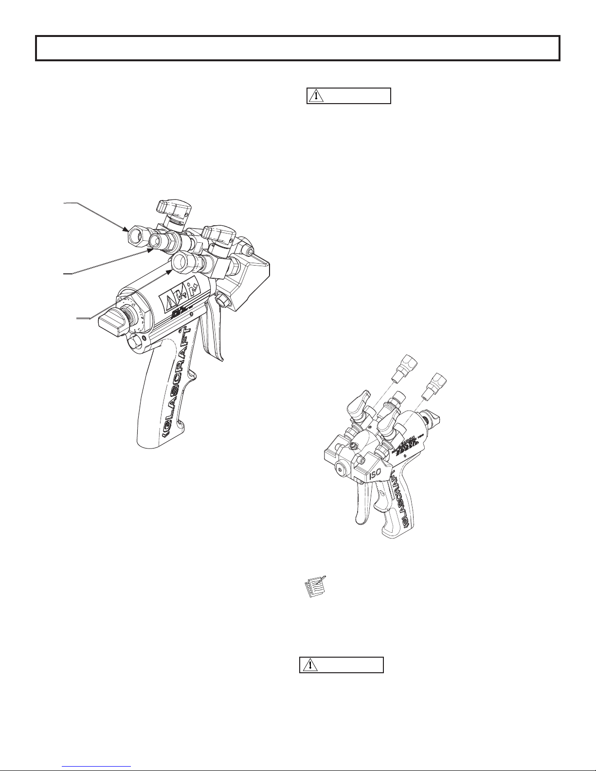
GlasCraft Equipment
Air Hose is ¼ in. NPS
JIC and SAE Fittings DO NOT require the use of PTFE
tape.
Once the ttings are attached and tight, refer to system
manuals for start-up instructions.
*Fitting GC2394 is an unattached part that may need to be
connected to the air hose rst, depending on air hose tting,
then connected to the gun.
Installing P2 on Other Equipment
Do not place any part of the body in the path of the
material spray. Do not point the gun at or near other
personnel. Do not look into the mixing chamber ori-
ce at any time. Because of the hazardous materials
used in this equipment, it is recommended that the
operator use an air mask, goggles, protective cloth-
ing, and other safety equipment as prescribed by
current regulations, recommendations of the chemi-
cal suppliers, and the laws in the area where the
equipment is being used.
If original equipment does not require the use of an un-
heated whip hose or isolation hose, the P2 can be directly
installed on to the material hose.
Remove the ttings from the original gun.1.
Remove swivel ttings from ball valves. Ball valves 2.
are 1/8 in. NPT female. Remove swivel tting from
air slide valve. The air slide valve is a ¼ in. NPSM.
Install the original ttings into ball valves.3.
It is recommended to use a non-permanent thread
lock on the 1/8 in. NPT threads to assist as a sealant
and keep the ttings from twisting with gun move-
ment.
Install the gun on the original hoses.4.
Relieve ALL system uid and air pressure according
to manufacturer’s instructions.
WARNING
WARNING
ti21610a
ISO
*AIR
POLY
ti21609a
Questo manuale è adatto per i seguenti modelli
6
Indice


