Hach NX7500 Manuale utente

DOC023.L1.90581
NX7500
04/2018, Edition 4
User Manual
Bedienungsanleitung
Manuale utente
Manuel de l’utilisateur
Manual del usuario
Manual do utilizador
Návod k použití

English..............................................................................................................................3
Deutsch.......................................................................................................................... 19
Italiano............................................................................................................................ 35
Français......................................................................................................................... 51
Español.......................................................................................................................... 67
Português...................................................................................................................... 83
Čeština........................................................................................................................... 99
2

Table of contents
Specifications on page 3 Maintenance on page 15
General information on page 5 Troubleshooting on page 16
Installation on page 8 Replacement parts and accessories on page 17
Operation on page 13
Legal information
Manufacturer: TriOS Mess- und Datentechnik GmbH
Distributor: Hach Lange GmbH
The translation of the manual is approved by the manufacturer.
Specifications
Specifications are subject to change without notice.
Specification Details
Detector type High-end miniature spectrometer, 256 channels
UV: 200 to 360 nm (0.8 nm/pixel)
Light source Xenon flash lamp
Parameter Nitrate, Nitrite, TSSeq, SAC254, CODeq, BODeq, TOCeq, DOCeq, KHP, COD-SAKeq, BOD-
SAKeq, Abs210, Abs254, Abs360
Dimensions (Ø x L) 48.3 mm (1.9 in) x 460 mm (18.1 in)
Cable length 10 m (32.8 ft) attached at the probe, maximum 30 m (98.4 ft) by extension cables
Enclosure Stainless steel 1.4571/1.4404 or titanium 3.7035
Weight Stainless steel 3 kg (6.61 lb), titanium 2 kg (4.41 lb)
Protection class Immersion probe, 30 m (98.4 ft) water depth maximum
Pressure 3 bar maximum, in the flow cell 1 bar maximum, 2 to 4 L/min
Flow rate 0.1 to 10 m/s
Power requirements The controller supplies power to the probe
Power consumption Less than 8 W
Interface 8-pole M12 plug
Operating temperature 0 °C to 40 °C (32 °F to 104 °F), internal temperature compensation
Storage temperature –20 °C to 80 °C (–4 °F to 176 °F)
Optical path length 0.3, 1, 2, 5, 10 and 50 mm (0.01, 0.04, 0.08, 0.2, 0.39 and 1.97 in)
Certifications CE
Warranty EU: 2 years, US: 1 year
English 3

Table 1 Specifications—0.3 mm (0.01 in) optical path
Parameter Measuring range Detection limit 1
Nitrate, NO3-N 1 to 330 mg/L 1 mg/L
Nitrite, NO2-N 1.7 to 500 mg/L 1.7 mg/L
CODeq/BODeq 100 to 7300 mg/L 100 mg/L
DOCeq/TOCeq 17 to 3300 mg/L 17 mg/L
Table 2 Specifications—1 mm (0.04 in) optical path
Parameter Measuring range Detection limit 2
Nitrate N-NO30.3 to 100 mg/L 0.3 mg/L
Nitrite N-NO20.5 to 150 mg/L 0.5 mg/L
CODeq/BODeq 30 to 2200 mg/L 30 mg/L
DOCeq/TOCeq 5 to 1000 mg/L 5 mg/L
Table 3 Specifications—2 mm (0.08 in) optical path
Parameter Measuring range Detection limit 2
Nitrate N-NO30.15 to 50 mg/L 0.15 mg/L
Nitrite N-NO20.25 to 75 mg/L 0.25 mg/L
CODeq/BODeq 15 to 1100 mg/L 15 mg/L
DOCeq/TOCeq 2.5 to 500 mg/L 2.5 mg/L
Table 4 Specifications—5 mm (0.2 in) optical path
Parameter Measuring range Detection limit 2
Nitrate N-NO30.06 to 20 mg/L 0.06 mg/L
Nitrite N-NO20.1 to 30 mg/L 0.1 mg/L
CODeq/BODeq 6 to 440 mg/L 6 mg/L
DOCeq/TOCeq 1 to 200 mg/L 1 mg/L
Table 5 Specifications—10 mm (0.39 in) optical path
Parameter Measuring range Detection limit 2
Nitrate N-NO30.03 to 10 mg/L 0.03 mg/L
Nitrite N-NO20.05 to 15 mg/L 0.05 mg/L
CODeq/BODeq 3 to 220 mg/L 3 mg/L
DOCeq/TOCeq 0.5 to 100 mg/L 0.5 mg/L
1The detection limit specification refers to a standard reference solution with lab conditions. For
probes with 0.3 mm optical path length, it is recommended to adjust NO3 and NO2 readings by
a factor calibration. Use standard solutions or grab samples with known values to calibrate the
probe.
2The detection limit specification refers to a standard reference solution with lab conditions.
4 English
Table 6 Specifications—50 mm (1.97 in) optical path
Parameter Measuring range Detection limit 2
Nitrate N-NO30.006 to 2 mg/L 0.006 mg/L
Nitrite N-NO20.01 to 3 mg/L 0.01 mg/L
CODeq/BODeq 0.6 to 44 mg/L 0.6 mg/L
DOCeq/TOCeq 0.1 to 20 mg/L 0.1 mg/L
General information
In no event will the manufacturer be liable for direct, indirect, special, incidental or consequential
damages resulting from any defect or omission in this manual. The manufacturer reserves the right to
make changes in this manual and the products it describes at any time, without notice or obligation.
Revised editions are found on the manufacturer’s website.
Safety information
N O T I C E
The manufacturer is not responsible for any damages due to misapplication or misuse of this product including,
without limitation, direct, incidental and consequential damages, and disclaims such damages to the full extent
permitted under applicable law. The user is solely responsible to identify critical application risks and install
appropriate mechanisms to protect processes during a possible equipment malfunction.
Please read this entire manual before unpacking, setting up or operating this equipment. Pay
attention to all danger and caution statements. Failure to do so could result in serious injury to the
operator or damage to the equipment.
Make sure that the protection provided by this equipment is not impaired. Do not use or install this
equipment in any manner other than that specified in this manual.
Use of hazard information
D A N G E R
Indicates a potentially or imminently hazardous situation which, if not avoided, will result in death or serious injury.
WARNING
Indicates a potentially or imminently hazardous situation which, if not avoided, could result in death or serious
injury.
CAUTION
Indicates a potentially hazardous situation that may result in minor or moderate injury.
N O T I C E
Indicates a situation which, if not avoided, may cause damage to the instrument. Information that requires special
emphasis.
English 5

Precautionary labels
Read all labels and tags attached to the instrument. Personal injury or damage to the instrument
could occur if not observed. A symbol on the instrument is referenced in the manual with a
precautionary statement.
This is the safety alert symbol. Obey all safety messages that follow this symbol to avoid potential
injury. If on the instrument, refer to the instruction manual for operation or safety information.
This symbol indicates that a risk of electrical shock and/or electrocution exists.
This symbol identifies the presence of a strong corrosive or other hazardous substance and a risk of
chemical harm. Only individuals qualified and trained to work with chemicals should handle chemicals
or perform maintenance on chemical delivery systems associated with the equipment.
This symbol indicates the presence of devices sensitive to Electro-static Discharge (ESD) and
indicates that care must be taken to prevent damage with the equipment.
This symbol indicates the need for protective eye wear.
Electrical equipment marked with this symbol may not be disposed of in European domestic or public
disposal systems. Return old or end-of-life equipment to the manufacturer for disposal at no charge to
the user.
Electromagnetic waves
WARNING
Multiple hazards. Do not disassemble the instrument for maintenance. If the internal components must
be cleaned or repaired, contact the manufacturer.
WARNING
Electromagnetic radiation hazard. Do not use the instrument in dangerous environments.
N O T I C E
This instrument is sensitive to electromagnetic and electromechanical interference. These interferences can have
an effect on the analysis performance of this instrument. Do not put this instrument near equipment that can
cause interference.
Obey the safety information that follows to operate the instrument in accordance with local, regional
and national requirements.
• Do not operate the instrument in hospitals and equivalent establishments or near medical
equipment, such as pace makers or hearing aids.
• Do not operate the instrument near highly flammable substances, such as fuels, highly flammable
chemicals and explosives.
• Do not operate the instrument near combustible gases, vapors or dust.
• Keep the instrument away from strong vibration or shock.
6 English

• The instrument can cause interference in immediate proximity to televisions, radios and
computers.
• The warranty does not cover improper use or wear.
Chemical and Biological Safety
D A N G E R
Chemical or biological hazards. If this instrument is used to monitor a treatment process and/or
chemical feed system for which there are regulatory limits and monitoring requirements related to
public health, public safety, food or beverage manufacture or processing, it is the responsibility of the
user of this instrument to know and abide by any applicable regulation and to have sufficient and
appropriate mechanisms in place for compliance with applicable regulations in the event of malfunction
of the instrument.
Normal operation of this device may require the use of chemicals or samples that are biologically
unsafe.
• Observe all cautionary information printed on the original solution containers and safety data
sheets prior to their use.
• Dispose of all consumed solutions in accordance with the local and national regulations and laws.
• Select the type of protective equipment suitable to the concentration and quantity of the dangerous
material being used.
Product overview
The NX7500 is a multi-parameter scanning UV probe. Refer to Figure 1. Use the probe for
photometric measurements in aqueous solutions in waste water, drinking water and environmental
applications.
The probe connects to a CD500 or a CD300 digital controller to monitor the measurement data,
calibration and configuration.
Figure 1 Product overview
1 Optical path with optical windows 4 Hanging ring
2 Probe 5 Probe cable with connector
3 Chain holder mount 6 Compressed air connector
English 7
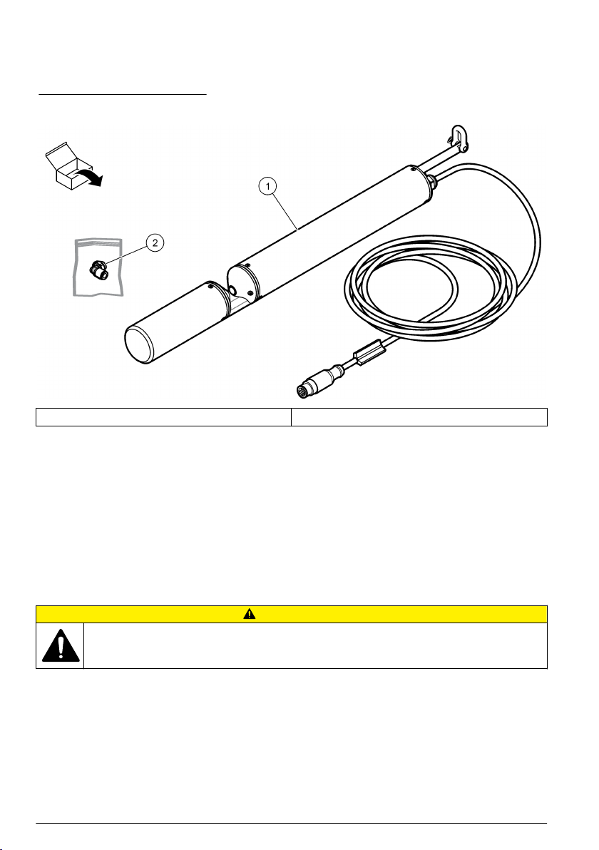
Product components
Make sure that all components have been received. Refer to Figure 2. If any items are missing or
damaged, contact the manufacturer or a sales representative immediately.
Figure 2 Product components
1 Probe 2 Compressed air connector
Theory of operation
The probe has a light source, a lens system, optical path through the medium and a spectrometer.
The probe uses a xenon flash lamp as a broadband light source. The light goes through the optical
path in the medium, and the medium absorbs some light. The spectrometer records the remaining,
spectrally resolved light and determines the intensity at multiple wavelengths in a wavelength range.
A measurement in ultrapure water calibrates the probe to zero (by the manufacturer).
The analysis software calculates the absorption value with concentrations or concentration
equivalents.
Installation
CAUTION
Multiple hazards. Only qualified personnel must conduct the tasks described in this section of the
document.
Installation guidelines
Note: Make sure that the enclosure of the probe is titanium before use in sea water.
• Do not use stainless steel probes in sea water or other corrosion-causing media (e.g., acids,
alkalis, chlorine-based compounds). Clean the probe immediately.
• Do not use titanium probes in bromine, hydrofluoric acid and hot acids. Clean the probe
immediately if the probe touches hydrofluoric acid or hot acids.
• The seals of the probe are made of NBR (nitrile butadiene rubber). Make sure that the measuring
medium does not cause damage to the probe components.
8 English

• Do not replace the cable. If the cable has damage, contact the manufacturer.
• Make sure that the cable is not routed near hot surfaces. Make sure not to put heavy objects on
the cable.
• Make sure that there are no unwanted materials in the optical path.
• Immediately set the instrument to OFF if the probe sends out smoke, noxious fumes or gets hot.
Contact the manufacturer.
Installation overview
Figure 3 shows an example of the probe installation with a chain holder option. Figure 4 shows an
example of the probe installation with a flow cell option. Refer to the installation documentation to
install the sensor.
Put the probe into the sample. Make sure that the optical path is fully immersed in the sample. Install
the sensor transversally to the flow direction of the sample so the particle on the windows are at a
minimum and the nano-layer function gives the optimum support. Refer to Figure 5.
Note: Make sure that the probe does not touch the ground.
Figure 3 Chain holder installation
English 9

Figure 4 Sensor with flow cell installation
1 Outflow, 6 mm OD 3 Flow cell
2 Connector for cleaning fluid 4 Inflow, 8 mm OD
Figure 5 Flow direction
Connect the probe to the controller
N O T I C E
Never connect the sensor to the controller when the controller is energized or damage to the sensor can
occur.
The probe has a 10 m fixed cable with an M12 industrial plug that connects to a digital controller for
signal transmission and power. Refer to Figure 6 and Figure 7.
10 English
Indice
Lingue:


