SUTO S415 Manuale

English
Instruction and Operation Manual
S415
Compact Thermal Mass Flow Meter
(Eco-Inline)

Dear Customer,
Thank you for choosing our product.
Before you start up the device please read the operating instructions in
full and carefully observe them. The manufacturer cannot be held liable
for any damage which occurs as a result of non-observance or non-
compliance with this manual.
Should the device be tampered with in any manner other than a
procedure which is described and specified in the manual, the warranty
is canceled and the manufacturer is e empt from liability.
The device is destined e clusively for the described application.
SUTO offers no guarantee for the suitability for any other purpose.
SUTO is also not liable for consequential damage resulting from the
delivery, capability or use of this device.
2 S415

Ta le of Contents
1 Safety Instructions......................................................................4
2 Registered Trademarks................................................................6
3 RF E posure Information and Statement........................................7
4 Application.................................................................................8
5 Features....................................................................................8
6 Technical Data............................................................................9
6.1 General Data........................................................................9
6.2 Electrical Data.....................................................................10
6.3 Output Signals....................................................................10
6.4 Accuracy ...........................................................................10
7 Dimensional Drawing.................................................................11
8 Installation...............................................................................14
8.1 Installation Considerations....................................................14
8.2 LED Indicators....................................................................15
8.3 Electrical Connection ..........................................................15
9 Signal Outputs..........................................................................17
9.1 Analog Output.....................................................................17
9.2 Pulse Output.......................................................................17
9.3 Modbus Interface.................................................................18
9.3.1 Modbus Information.......................................................18
9.3.2 Connect Several S415 to Modbus Master...........................19
9.3.2.1 Modbus/RTU Cable Length.........................................19
9.3.2.2 Modbus/RTU Wiring and Cable Type............................20
9.3.2.3 Create Daisy-Chain using RS-485 Splitter....................21
9.3.2.4 Topology of Modbus/RTU Daisy-Chain.........................22
9.4 M-Bus Output......................................................................23
9.5 Connection between S415 Outputs and Customer Equipment....23
10 Configuration..........................................................................25
11 Calibration..............................................................................26
12 Disposal or Waste....................................................................26
13 Appendi A - Specifications.......................................................27
13.1 Flow Ranges......................................................................27
13.2 Error Code........................................................................28
13.3 Order Table.......................................................................28
S415 3
1 Safety Instructions
1 Safety Instructions
Please check if this instruction manual matches the
product type.
Please observe all notes and instructions indicated in this
manual. It contains essential information which must be
observed before and during installation, operation, and
maintenance. Therefore this instruction manual must be read carefully
by the technician as well as by the responsible user / qualified
personnel.
This instruction manual must be available at the operation site of the
flow meter at any time. In case of any obscurities or questions,
regarding this manual or the product, please contact the manufacturer.
WARNING!
Compressed air!
Any contact with quickly escaping air or ursting
parts of the compressed air system can lead to
serious injuries or even death!
•Do not e ceed the ma imum permitted pressure range (see
sensors label).
•Only use pressure tight installation material.
•Avoid that persons get hit by escaping air or bursting parts of the
instrument.
•The system must be pressureless during maintenance work.
WARNING!
Voltage used for supply!
Any contact with energized parts of the product
might lead to an electrical shock which can lead to
serious injuries or even death!
•Consider all regulations for electrical installations.
•The system must be disconnected from any power supply during
maintenance.
•Any electrical work on system is only allowed by authorized
qualified personal.
4 S415
1 Safety Instructions
ATTENTION!
Permitted operating parameters!
O serve the permitted operating parameters. Any
operation exceeding this parameters can lead to
malfunctions and might lead to damage on the
instrument or the system.
•Do not e ceed the permitted operating parameters.
•Make sure the product is operated in its permitted limitations.
•Do not e ceed or undercut the permitted storage and operating
temperature and pressure.
•The product should be maintained and calibrated frequently, at
least annually.
General safety instructions
•It is not allowed to use the product in e plosive areas.
•Please observe the national regulations before/during installation
and operation.
Remarks
•It is not allowed to disassemble the product.
ATTENTION!
Measurement values can e affected y malfunction!
The product must e installed properly and
frequently maintained. Otherwise it might lead to
wrong measurement values, which can result in
wrong results.
•Always observe the direction of the flow when installing the
device. The direction is indicated on the housing.
•Do not e ceed the ma imum operating temperature at the sensors
tip.
•Avoid condensation on the sensor element as this will affect
accuracy enormously.
S415 5

1 Safety Instructions
Storage and transportation
•Make sure that the transportation temperature is between
-30 ... +70°C.
•For storage and transportation it is recommended to use the
packaging which comes with the device.
•Make sure that storage temperature of the device is between
-10 ... +50°C.
•Avoid direct UV and solar radiation during storage.
•For the storage the humidity must be <90% with no condensation.
2 Registered Trademarks
Trademark Trademark owner
SUTO®SUTO iTEC
MODBUS®Modbus Organization, Hopkinton, USA
Android™,
Google Play
Google LLC
6 S415

3 RF Exposure Information and Statement
3 RF Exposure Information and Statement
This equipment complies with FCC RF radiation e posure limits set forth
for an uncontrolled environment. This equipment should be installed
and operated with minimum distance of 20 cm between the radiator and
your body.
This device complies with part 15 of the FCC rules. Operation is subject
to the following two conditions: (1) this device may not cause harmful
interference, and (2) this device must accept any interference received,
including interference that may cause undesired operation.
NOTE: The manufacturer is not responsible for any radio or TV
interference caused by unauthorized modifications to this equipment.
Such modifications could void the user’s authority to operate the
equipment.
NOTE: This equipment has been tested and found to comply with the
limits for a Class B digital device, pursuant to part 15 of the FCC Rules.
These limits are designed to provide reasonable protection against
harmful interference in a residential installation. This equipment
generates uses and can radiate radio frequency energy and, if not
installed and used in accordance with the instructions, may cause
harmful interference to radio communications. However, there is no
guarantee that interference will not occur in a particular installation. If
this equipment does cause harmful interference to radio or television
reception, which can be determined by turning the equipment off and
on, the user is encouraged to try to correct the interference by one or
more of the following measures:
•Reorient or relocate the receiving antenna.
•Increase the separation between the equipment and receiver.
•Connect the equipment into an outlet on a circuit different from
that to which the receiver is connected.
•Consult the dealer or an e perienced radio/TV technician for help
•This device and its antenna(s) must not be co-located or operating
in conjunction with any other antenna or transmitter.
S415 7

4 Application
4 Application
The S415 is the thermal mass flow meter that is designed to measure
the volumetric flow and consumption of compressed air and nitrogen
within the permitted operating parameters. (See Technical Data on the
ne t page.)
The default unit settings are: volumetric flow in l/min and total
Consumption in m3. Other units can be configured using the mobile App
S4C-FS, which can be downloaded from the Google Play store or SUTO
website. For more information, see chapter 10 on page 25.
5 Features
•Inline thermal mass flow meter virtually independent of pressure
and temperature changes
•Process connection G-type thread, DN8, DN15, DN20, DN25 and
DN32
•Integrated flow conditioner, no need of straight inlet sections
•Very short response time
•Particularly suitable for measuring at point-of-use flow and
consumption of compressed air or N2
•Integrated display showing volumetric flow
•Choices of output signals:
◦Analogue 4 … 20 mA and pulse output
◦Modbus interface
◦M-Bus interface
•Bluetooth interface for device settings
•Configurable through the mobile phone App S4C-FS
8 S415
6 Technical Data
6 Technical Data
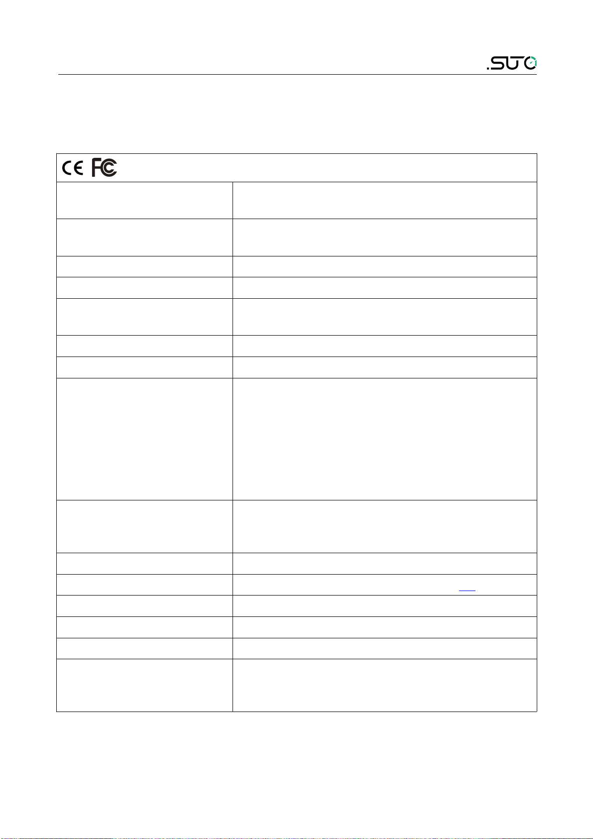
6.1 General Data
FCC ID: 2ASK2-SUTO-002
Parameters Standard unit flow: l/min (default)
Consumption units: m³ (default)
Reference conditions ISO1217 20°C, 1000 hPa (Standard-Unit)
DIN1343 0°C , 1013.25 hPa (Norm-Unit)
Principle of measurement Thermal mass flow
Sensor Glass coated resistive sensor
Ambient temperature
/Transport temperature
0 ... +50°C / -30 ... +70°C
Medium conditions 0 ... +50°C, rH<90% no condensation
Operating pressure 0 ... 1.0 MPa
Pressure drop Ma imum pressure drop at the ma imum
flow of the Standard (S) flow range:
•DN8 type : 30 hPa
•DN15 type: 100 hPa
•DN20 type: 100 hPa
•DN25 type: 200 hPa
•DN32 type: 170 hPa
Casing Process connection: aluminum alloy
Wetted parts: aluminum alloy
Top casing: PC + ABS
Protection class IP54
Dimensions See dimensional drawing on page 11.
Display 4-digit LED display
Tube diameter DN8, DN15, DN20, DN25, and DN32
Process connection G inner thread ISO 228-1
Weight 0.45 kg (DN8), 0.44 kg (DN15)
0.97 kg (DN20), 0.94 kg (DN25)
1.7 kg (DN32)
S415 9

6 Technical Data
6.2 Electrical Data
Power supply 15 ... 30 VDC, 120 mA @ 24 VDC
6.3 Output Signals
Analogue output Signal: 4 ... 20 mA, isolated
Scaling: 0 to ma flow
Ma load: 250R
Pulse output 1 pulse per m3 , isolated switch, ma .
30 VDC, 200 mA
(pulse length: 10 ... 120 ms, depends on flow
rate)
Modbus output See section 9.3 on page 18.
6.4 Accuracy
Accuracy*
(at 6 bar, 20°C, rH<40%)
± (3.0% of reading + 0.3% Full Scale)
Temperature coefficient < 0.1%/K Full Scale
Pressure coefficient <5% / 1 MPa
Turndown ratio 50 : 1
Stated accuracy at Ambient/process temperature 23°C ± 3°C
Ambient/process humidity <90%
Process pressure at 0.6 MPa
Repeatability ±1% of reading
Sampling rate 3 samples per second
* The specified accuracy is valid only within the minimum and ma imum
flow rates that are stated in section 13.1 on page 27.
Remark:
The total consumption value is saved to the permanent memory every 5
minutes. If within these 5 minutes the device is powered off, it will
restore the last consumption value which was saved in the last cycle.
10 S415
Altri manuali per S415
2
Indice
Altri manuali SUTO Strumento di misura


